medical laryngeal mask
A laryngeal mask and laryngeal tube technology, applied in the field of medical laryngeal masks, can solve the problems of interrupted air supply, unreliability, and entering patients, and achieve the effects of improving reliability, increasing reliability, and saving time
- Summary
- Abstract
- Description
- Claims
- Application Information
AI Technical Summary
Problems solved by technology
Method used
Image
Examples
Embodiment 1
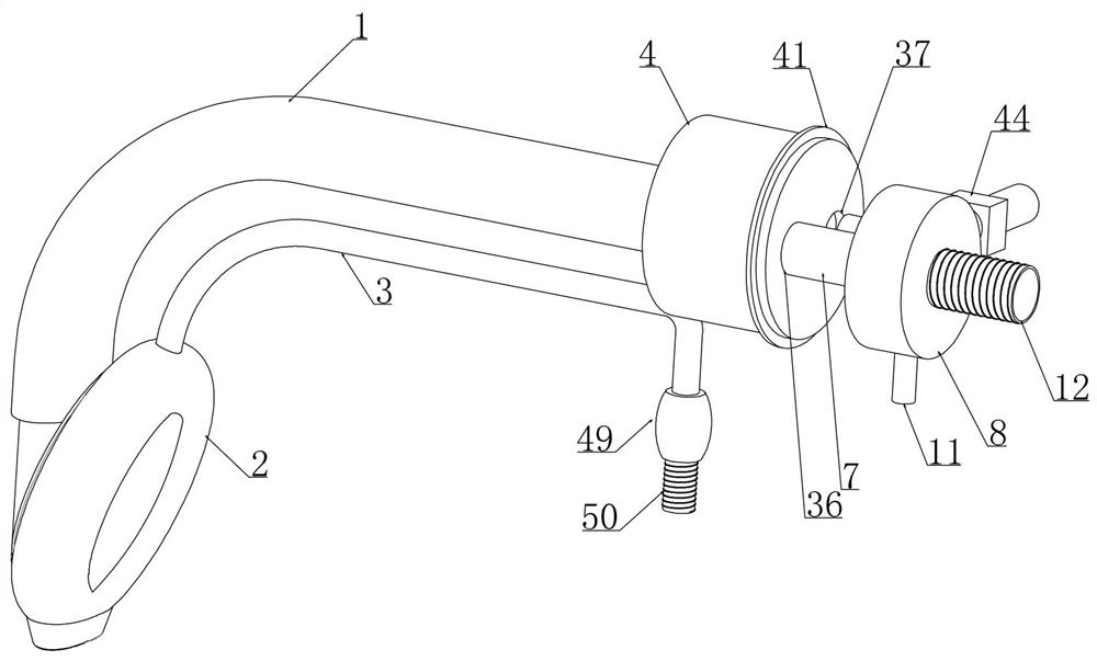
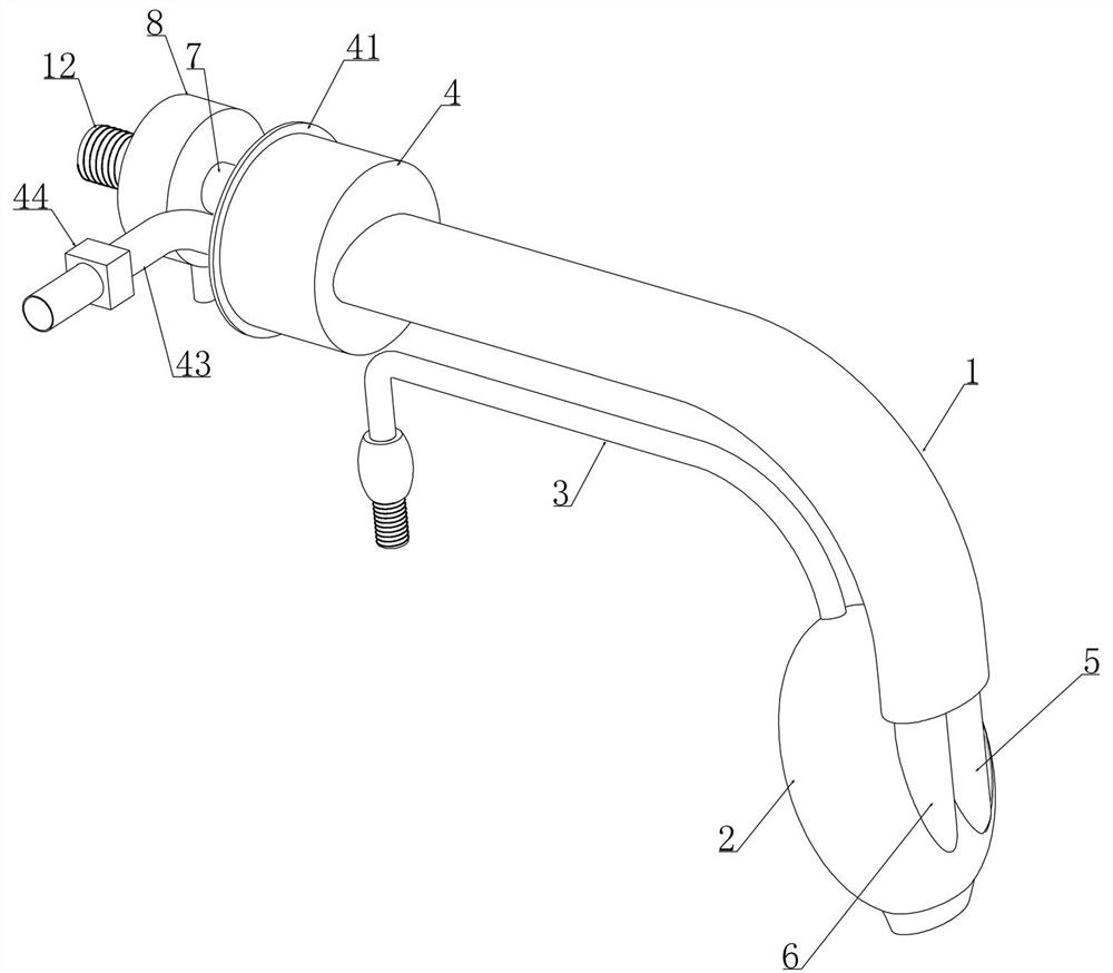
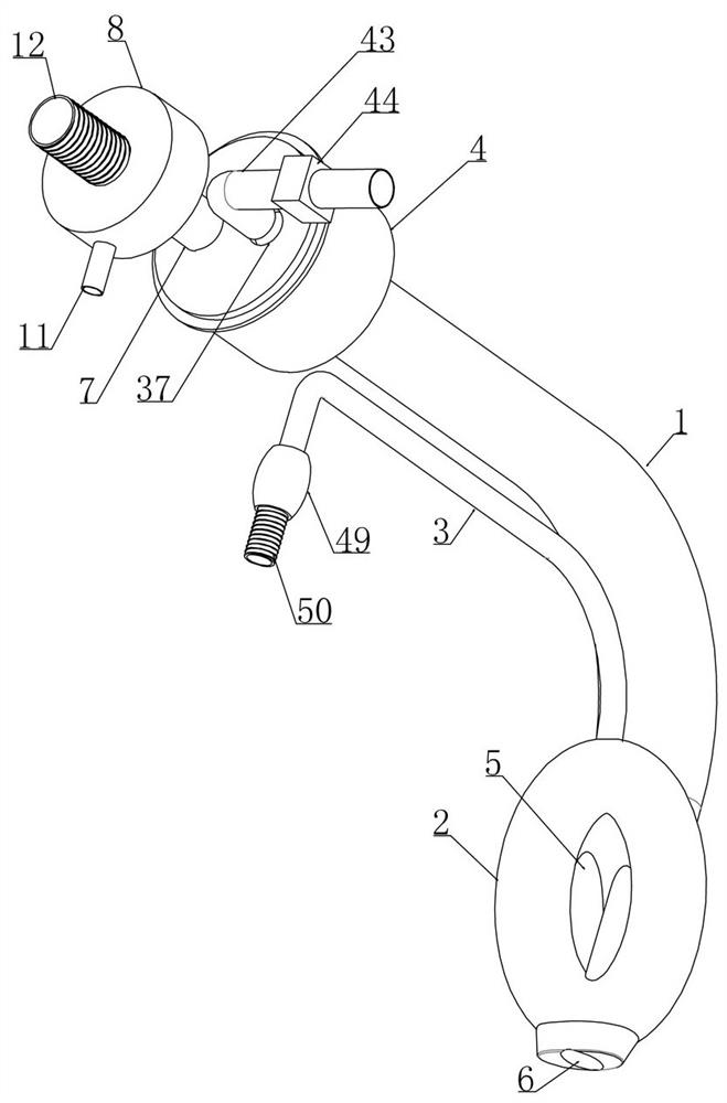
[0045] Embodiment 1, a medical laryngeal mask, includes a throat 1 and a cuff 2 is connected to the opening of the front section of the throat 1, and the cuff 2 is connected to an inflatable tube 3. It is characterized in that the other end of the throat 1 is connected to a cylinder A tube 4, the throat 1 is longitudinally provided with an air passage 5 and a drainage channel 6, and the air passage 5 and the drainage channel 6 communicate with the cylindrical tube 4 respectively, and the end of the cylindrical tube 4 away from the throat 1 is provided with a drainage channel seal device, the cylindrical barrel 4 is horizontally slidably connected with a connecting pipe 7 matching with the air passage 5 and a positioning device is arranged in the cylindrical barrel 4, and an unlocking device is provided at the sliding matching part of the connecting pipe 7 and the cylindrical barrel 4, so The connecting pipe 7 passes through the side wall of the cylindrical tube 4 and extends ou...
Embodiment 2
[0051] Embodiment 2, on the basis of Embodiment 1, the annular ring 9 includes a first circular ring 13 and a second circular ring 14 arranged transversely and concentrically, and the first circular ring 13 and the second circular ring 14 are arranged vertically The two sides are fixedly connected by U-shaped sliders 15, and the two rings are laterally slidably connected to the inner wall of the connecting pipe 7 through two U-shaped sliders 15, and the inner wall of the connecting pipe 7 is provided with a rectangular slideway that is slidably matched with the U-shaped sliders 15 16. Two first rectangular sliding rails 17 are fixedly connected to the semicircular ring on the longitudinal side of the first circular ring 13 at intervals along its diameter direction, and the arc-shaped scraper 10 is slidably fitted to the corresponding first In the rectangular slide rail 17, the two arc-shaped scrapers 10 and the first circular ring 13 are slidingly fitted and spaced from the sec...
Embodiment 3
[0053] Embodiment 3. On the basis of Embodiment 2, the drive device includes: the first ring 13 and the second ring 14 are respectively fixedly connected with connecting rods 19 through their circle centers, and the center positions of the two connecting rods 19 are fixedly connected with inner rings. Threaded cylinder 20, the internally threaded cylinder 20 is fitted with a drive screw 21 that is rotatably mounted on the connecting pipe 7 and coaxially arranged with the connecting pipe 7 through threads, and the drive screw 21 is driven by a motor 22 fixed in the transfer chamber 8 , the motor controller is electrically connected to the microcontroller.
[0054] When this embodiment is in use, how the driving device works will be described in detail below; the first circular ring 13 and the second circular ring 14 are respectively fixedly connected with connecting rods 19 and the two connecting rods 19 through their center positions. The central part is fixedly connected with...
PUM
 Abstract
Description
Claims
Application Information
 - R&D
- Intellectual Property
- Life Sciences
- Materials
- Tech Scout
- Unparalleled Data Quality
- Higher Quality Content
- 60% Fewer Hallucinations
Browse by: Latest US Patents, China's latest patents, Technical Efficacy Thesaurus, Application Domain, Technology Topic, Popular Technical Reports.
© 2025 PatSnap. All rights reserved.Legal|Privacy policy|Modern Slavery Act Transparency Statement|Sitemap|About US| Contact US: help@patsnap.com


