Mixing equipment for polycarbonate modified material

A modified material, polycarbonate technology, applied in mixers, mixers with rotating containers, dissolution, etc., can solve problems such as inability to achieve mixing, reduced cleanliness of mixing tanks, and single mixing methods for raw materials

Pending Publication Date: 2019-09-20
南京清研新材料研究院有限公司
View PDF0 Cites 5 Cited by
  • Summary
  • Abstract
  • Description
  • Claims
  • Application Information

AI Technical Summary

Problems solved by technology

[0002] During the preparation process of polycarbonate modified materials, raw materials usually need to be mixed and stirred. The existing mixing method of raw materials is relatively simple. The motor rotates the stirring rod through the stirring shaft to realize the mixing. Due to the fixed position of the motor, Calmness makes the working range of the stirring rod limited, and it is impossible to achieve sufficient, efficient and uniform mixing. After the raw materials are mixed and stirred once, they are usually discharged directly for subsequent processing. After the raw materials are stirred and mixed once, there may still be insufficient Due to the existence of mixed particles, the direct subsequent processing of raw materials after one-time mixing may lead to poor quality of the produced products. During the mixing operation, the inner end wall of the mixing tank will inevitably have raw material particles adhered to it. The adhesion of raw material particles will not only cause waste of raw materials but also reduce the cleanliness inside the mixing tank, so now a kind of mixing equipment for polycarbonate modified materials is needed

Method used


Image

  • Mixing equipment for polycarbonate modified material
  • Mixing equipment for polycarbonate modified material
  • Mixing equipment for polycarbonate modified material

Examples


Embodiment 1

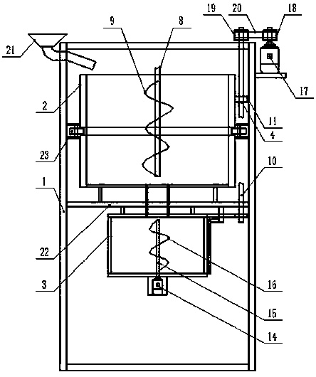
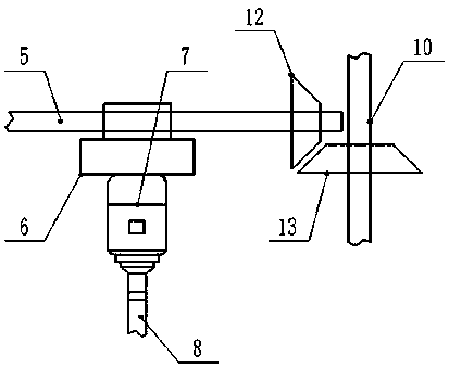
[0013] Embodiment 1: see figure 1 , figure 2 , image 3 , Figure 4 , a kind of mixing equipment for polycarbonate modified materials provided by the present invention is now described, including a mixing box 1, and a primary mixing tank 2 is provided on the middle side of the upper end of the inner cavity of the mixing box 1, and the A secondary mixing tank 3 is provided in the mixing box 1 and located on the middle side below the position of the primary mixing tank 2, and a mixing assembly 4 is provided at the upper end of the inner cavity of the mixing box 1, and the mixing assembly 4 is the screw mandrel 5 that is provided on the middle side of the top end of the mixing box 1, the sliding seat 6 provided at the lower end of the screw mandrel 5, the first motor 7 provided at the lower end of the sliding seat 6, and the first motor 7 vertically The downward output shaft is connected to the first agitating shaft 8 by a coupling, the first agitating blade 9 provided on the...

Embodiment 2

[0014] Example 2: see figure 1 , figure 2 , Figure 4Now, a kind of mixing equipment for polycarbonate modified materials provided by the present invention will be described. A third motor 17 is provided on the outer wall of the top end of the mixing box 1, and the output of the third motor 17 is vertically upward. A driving pulley 18 is sleeved on the shaft, and the top end of the transmission shaft 10 moves through the inner top wall of the mixing box 1 to protrude and its protruding end is covered with a driven pulley 19. The driving pulley 18 A belt 20 is set between the outside of the driven pulley 19, the mixing box 1 is a hollow cylinder, and the top side wall of the mixing box 1 has a feed port, and the mixing box 1 A feed funnel 21 is arranged on the outer side of the top of the casing 1, and the discharge end at the bottom of the feed funnel 21 is communicated with the feed inlet through a pipeline. The feed end of the guide pipe is connected to the feed port, th...

Embodiment 3

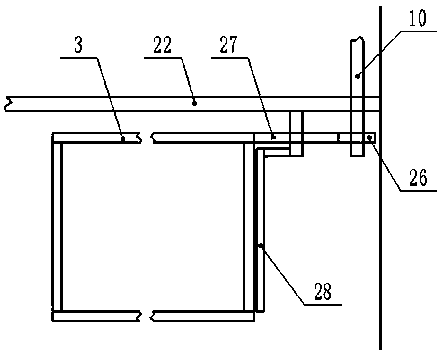
[0015] Embodiment 3: see figure 1 , image 3 , the mixing equipment for a polycarbonate modified material provided by the present invention is now described, the secondary mixing tank 3 includes an upper disc-shaped frame, a lower disc-shaped frame and an upper disc-shaped frame It is composed of a cylindrical filter frame provided between the lower disc-shaped frame body. The cylindrical filter frame is uniformly and densely opened with filter holes, and the upper end of the upper disc-shaped frame body is provided with an annular chute and the annular An annular slider is movable in the chute, and a vertical frame is evenly arranged between the upper end of the annular slider and the lower end of the fixed frame 22, and a circular discharge opening is opened in the middle of the bottom of the primary mixing tank 2 And the circular material discharge port is vertically connected downward with a material guide tube, the middle part of the top of the secondary mixing tank 3 ha...


PUM


Abstract

The invention discloses mixing equipment for a polycarbonate modified material. The mixing equipment comprises a mixing box body; an inner cavity of the mixing box body is provided with a primary mixing barrel and a secondary mixing barrel; the upper end of the inner cavity of the mixing box body is provided with a mixing component; the mixing component is composed of a screw rod, a sliding seat, a first motor, a first stirring shaft, a first stirring blade, a transmission shaft, a first transmission gear, a driven gear and a driving gear; the middle of the outer bottom end of the secondary mixing barrel is provided with a second motor; the middle side of the inner end of the secondary mixing barrel is vertically provided with a second stirring shaft, and the end part of the bottom end of the second stirring shaft is connected with an output shaft of the second motor by a coupling; and the second stirring shaft is sleeved with a second stirring blade.

Description

technical field [0001] The invention relates to the field of production and processing of polycarbonate modified materials, in particular to a mixing device for polycarbonate modified materials. Background technique [0002] In the preparation process of polycarbonate modified materials, raw materials usually need to be mixed and stirred. The existing mixing method of raw materials is relatively simple. The motor rotates the stirring rod through the stirring shaft to realize the mixing. Due to the fixed position of the motor, Calmness makes the working range of the stirring rod limited, and it is impossible to achieve sufficient, efficient and uniform mixing. After the raw materials are mixed and stirred once, they are usually discharged directly for subsequent processing. After the raw materials are stirred and mixed once, there may still be insufficient Due to the existence of mixed particulate matter, the direct subsequent processing of raw materials after one-time mixing...

Claims


Application Information

Patent Timeline
Patent Type & Authority Applications(China)
IPC IPC(8): B01F9/16B01F13/10B01F15/00B01F29/85
CPCB01F29/85B01F33/811B01F35/123
Inventor 张奇丁丽娜
Owner 南京清研新材料研究院有限公司
Why Eureka
Try Eureka