Conveying chain capable of automatically compensating and balancing tension

A technology of conveying chain and conveying device, applied in the direction of conveyor, conveyor object, conveyor control device, etc., can solve the problems of conveyor chain stop, conveyor chain relaxation, affecting the smooth conveying of conveyor chain, etc., to improve adaptability and reliability. Tone, avoid the effect of frequent movements

Pending Publication Date: 2019-09-20
CITIC DICASTAL
View PDF0 Cites 2 Cited by
  • Summary
  • Abstract
  • Description
  • Claims
  • Application Information

AI Technical Summary

Problems solved by technology

In the actual production process of the wheel hub, the size and weight of the on-site production wheel are variable, and the chain load of the spraying line changes dynamically with the wheel type switching. With the accumulation of years of production, the conveyor chain will produce different degrees of stretching. In addition , when the load of the conveyor chain changes, especially when the load weight increases, the conveyor chain is pressed do

Method used


Image

  • Conveying chain capable of automatically compensating and balancing tension
  • Conveying chain capable of automatically compensating and balancing tension
  • Conveying chain capable of automatically compensating and balancing tension

Examples


Embodiment 1

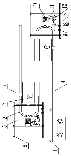
[0025] Attached below Figure 1-3 Description of Embodiment 1 of the present application: a conveyor chain with automatic compensation and balanced tension, including a drive station 1, a conveyor chain, a sliding bracket, a telescopic guide rail, a sliding trolley 5, a trolley sliding rail 6, a counterweight tensioning assembly 7, Guide rail alarm limit switch 8, guide rail warning limit switch 9, guide rail position maintenance component. The driving station 1 provides the driving force to drive the conveying direction of the conveying chain. The conveying chain is arranged in the telescopic guide rail, and the sliding bracket is arranged on the conveying chain. The sliding support is used to carry the objects to be conveyed. The chain drives the sliding support and the objects to be conveyed on the sliding support to move towards the conveying direction.

[0026] It includes two sliding trolleys 5 and two trolley sliding rails 6, one sliding trolley 5 corresponds to one tr...

Embodiment 2

[0033] Embodiment 2: The difference between embodiment 2 and embodiment 1 is that the guide rail warning limit switch 9 and the guide rail position maintaining component are only arranged on the proximal side of the driving station 1 . Specifically in embodiment 2: the delivery device also includes a guide rail early warning limit switch 9 and a guide rail position maintenance assembly, the guide rail early warning limit switch 9 is located on the trolley slide rail 6 at the near end of the drive station 1, and is located at the guide rail alarm limit switch Before the switch 8; the guide rail position maintenance component is arranged on the outside of the sliding trolley 5 at the proximal end of the drive station 1, and is used to apply to the sliding trolley 5 or the U-shaped An inward force of the curved rail 2 makes the sliding trolley 5 or the U-shaped curved rail 2 no longer move outward until the object to be conveyed is transferred to the telescopic guide rail at the f...

Embodiment 3

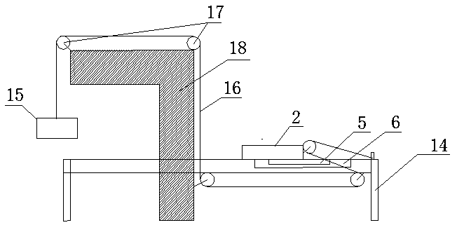
[0034] Embodiment 3: The difference between embodiment 3 and embodiment 1 is that the structure of the counterweight tensioning assembly 7 is different, specifically in embodiment 3: a guide rail bracket 14 is set under the telescopic guide rail, and the guide rail bracket 14 is used to support the telescopic guide rail and the trolley sliding rail 6; the U-shaped bottom of each U-shaped curved rail 2 is connected with a counterweight tensioning assembly 7, and the counterweight tensioning assembly 7 includes a counterweight 15, a counterweight bracket 18, Wire rope 16, pulley assembly 17, counterweight support 18 comprises vertical part and horizontal part, and the top of vertical part connects horizontal part; On the horizontal part of the heavy support 18, the fixed pulley at one end of the vertical part, the fixed pulley in the middle of the bottom surface of the end where the U-shaped curved rail 2 is located on the guide rail support 14, and the steel rope 16 one ends are...


PUM


Abstract

The invention belongs to the technical field of conveying devices, and particularly relates to a conveying chain capable of automatically compensating and balancing tension. The conveying chain comprises a driving station, a conveying chain, a sliding support, a telescopic guide rail, a sliding trolley, a trolley sliding rail, a counterweight tensioning assembly, a guide rail warning limit switch, a guide rail early warning limit switch and a guide rail position maintaining assembly, through the arrangement of the telescopic guide rail and the counterweight tensioning assembly, the conveying chain can automatically adjust the telescopic, tensioning and balancing of the guide rail, and the conveying efficiency of the conveying chain is prevented from being influenced by loosening of the conveying chain; a guide rail early warning limit switch and a guide rail position maintaining assembly are additionally arranged, the guide rail position maintaining assembly provides a reverse compensation force for the telescopic guide rail within a certain time when the guide rail early warning limit switch is triggered, the imbalance of the moving amount of the sliding trolley is reduced, the sliding trolley at the near end or the far end of the driving station can be prevented from triggering the limit position signal to give an alarm in advance, the whole conveying chain can not be shut down, so that the dynamic balance of tensioning stations at two positions can be guaranteed, and the tightness change of the chain can be completely counteracted.

Description

technical field [0001] The present application relates to the technical field of conveying devices, in particular to a conveying chain with automatic compensation and balanced tension. Background technique [0002] Coating conveyor chain is a kind of assembly line conveying equipment that is widely used. The conveyor chain is non-standard equipment. Customers can customize it according to the process requirements. The chain production line is mainly composed of three parts: conveyor frame, chain, and power device. The conveyor frame is the main body. Partly, the chain is used as the conveying carrier, and the power unit is used to provide power for the operation of the equipment. With the advancement of science and technology and industrial production, the conveying chain technology has achieved rapid development in many fields such as wheel hubs and auto parts. In the actual production process of the wheel hub, the size and weight of the on-site production wheel are variabl...

Claims


Application Information

Patent Timeline
IPC IPC(8): B65G23/44B65G43/02
CPCB65G23/44B65G43/02B65G21/14B65G21/22B65G17/12B65G17/28B65G21/20B65G43/06
Inventor 陈林吕杰徐宏庆何文明王克彬郝进勇宁建朋马志英
Owner CITIC DICASTAL
Why Eureka
Try Eureka