
Drainage hole structure used for disposing ditch water of hydropower stations in alpine and canyon areas

A technology for ditch water treatment and drainage holes, which is used in hydropower stations, hydroelectric power generation, water conservancy projects, etc., can solve problems affecting the construction progress of previous projects, increasing the regular drainage intensity and drainage cost of the foundation pit of retaining dams, and long construction period, etc. problems, to avoid soil erosion, reduce water catchment in the foundation pit, reduce drainage intensity and drainage costs

Pending Publication Date: 2019-09-20
POWERCHINA CHENGDU ENG
View PDF0 Cites 0 Cited by
  • Summary
  • Abstract
  • Description
  • Claims
  • Application Information

AI Technical Summary

Problems solved by technology

[0004] The layout of the water inlet of the permanent drainage tunnel is limited by the utilization range of the valley and the location of the retaining dam for ditch water treatment. Generally, the permanent drainage tunnel is longer, the construction period is longer, and the excavation waste of the permanent drainage tunnel itself is also more. Therefore, according to It is conventionally considered that after the permanent drainage hole is completed and the water flow is completed, the abandoned slag will be piled up in the valley, which will directly affect the construction progress of other preliminary projects on the site, mainly including on-site roads, tunnels, bridges, substations, water plants, living camps and construction Leveling of the site, etc.; moreover, the accumulation of the excavation waste of the permanent drainage tunnel itself is also a difficult problem
In addition, the confluence of the tributary valley and the main river is located in the foundation pit of the retaining dam. After the permanent ditch water treatment project is put into use, the rainfall catchment below the permanent retaining dam to the confluence will still flow into the foundation pit of the retaining dam, which will greatly increase the retaining capacity. Regular drainage intensity and drainage cost in dam foundation pit

Method used


Image

  • Drainage hole structure used for disposing ditch water of hydropower stations in alpine and canyon areas
  • Drainage hole structure used for disposing ditch water of hydropower stations in alpine and canyon areas

Examples


Embodiment Construction

[0025] The present invention will be further described below in conjunction with accompanying drawing.

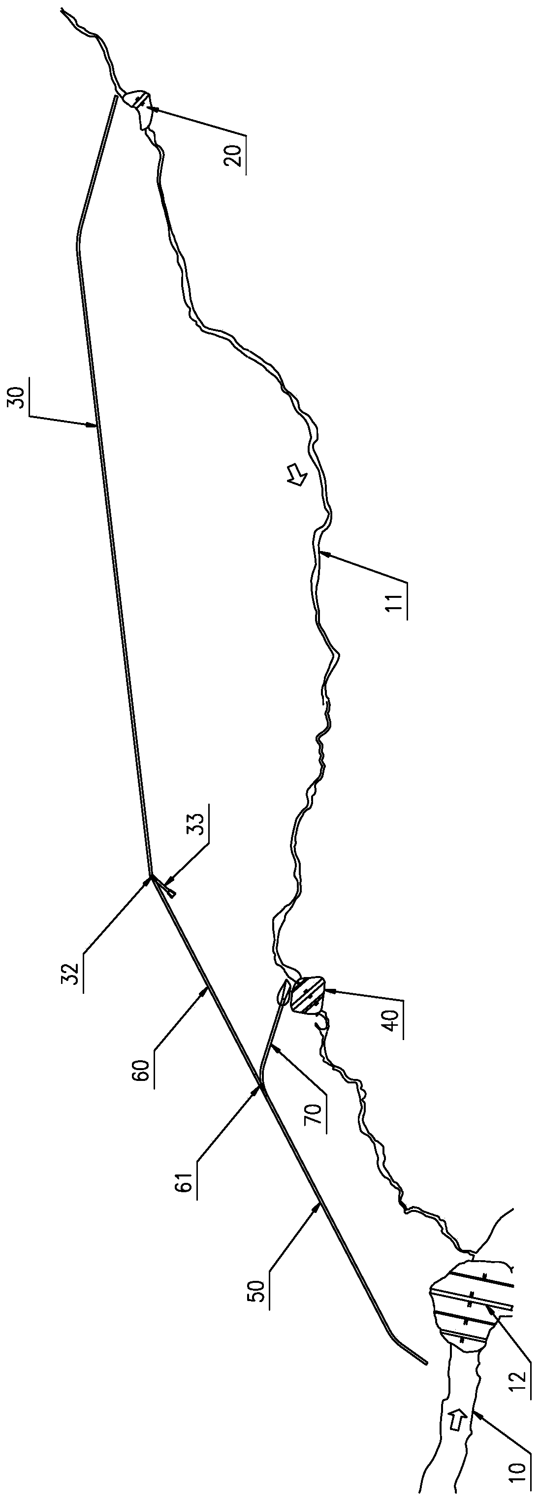
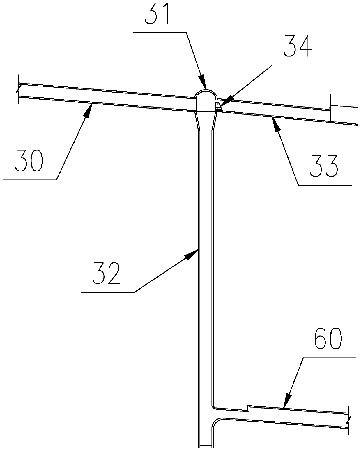
[0026] Such as figure 1 As shown, the drainage tunnel structure for hydropower station ditch water treatment in the alpine valley area includes permanent retaining dam 20, permanent drainage tunnel 30, temporary retaining dam 40, Yonglin drainage combined tunnel 50, Yonglin drainage connection tunnel 60 and the entrance section of the temporary drainage tunnel 70; the permanent retaining dam 20 is set on the tributary valley 11, the permanent drainage hole 30 is set in the mountain body, and the water inlet of the permanent drainage hole 30 is set in the tributary valley 11 on the upstream side of the permanent retaining dam 20; the temporary retaining dam 40 is set on On the tributary valley 11 on the downstream side of the permanent retaining dam 20, the water outlet of the permanent drainage hole 30 is located on the upstream side of the temporary retaining dam 40; The ...


PUM


Abstract

The invention belongs to the technical field of water conservancy and hydropower engineering, and particularly discloses a drainage hole structure used for disposing ditch water of hydropower stations in alpine and canyon areas and facilitating in-time stockpiling of excavated waste slag so as to ensure the construction progress of a hydropower station project, and a construction method for constructing the drainage hole structure. According to the drainage hole structure used for disposing the ditch water of the hydropower stations in the alpine and canyon areas, the parts on tributary valleys are filled with temporary water-retaining dams, inlet sections of a permanent and temporary drainage combination hole, a permanent and temporary drainage connection hole and a temporary drainage hole are arranged, under the premise of effectively disposing the ditch water of the tributary valleys, the tributary valleys can be cut off quickly, prior period slag stockpiling sites are formed at the ditch opening sections from the temporary drainage dams to the tributary valleys, the difficult problem that at the early state of the hydropower station project in the alpine and canyon areas, no construction waste slag site can be utilized is quickly solved, and thus project construction meets the water and soil conservation specification requirements that the waste slag is transported while being excavated, and the earth-rock waste slag generated by project excavation is transported to a planned slag site in time for centralized stacking.

Description

technical field [0001] The invention belongs to the technical field of water conservancy and hydropower engineering, and in particular relates to a drainage hole structure for treating ditch water of hydropower stations in alpine and valley areas. Background technique [0002] When constructing a hydropower station in an alpine valley area, when there is a tributary valley flowing into the retaining dam, consider water energy utilization and facilitate the layout of the water inlet or flood discharge tunnel entrance. Generally, the dam site is selected on the downstream side of the valley; after such an arrangement , during the construction period of the retaining dam, the confluence of the valley and the main river is located in the foundation pit of the retaining dam. Since there are very few construction sites available near the dam area, and a large amount of spoils need to be stockpiled during construction, according to the requirements of water and soil conservation re...

Claims


Application Information

Patent Timeline
IPC IPC(8): E02B9/06E02B8/06
CPCE02B9/06E02B8/06Y02E10/20
Inventor 王永刚相昆山孔科梁娟易文明张永清
Owner POWERCHINA CHENGDU ENG
Learn More