
A broadband high resolution large dynamic range delay compensation system and method

A large dynamic range, delay compensation technology, applied in the direction of instruments, installation, optics, etc., can solve problems such as poor compatibility, limited compensation performance improvement, complex structure, etc., to achieve the effect of improving overall performance and good compatibility

Active Publication Date: 2021-09-07
CHINA ACADEMY OF SPACE TECHNOLOGY
View PDF9 Cites 0 Cited by
  • Summary
  • Abstract
  • Description
  • Claims
  • Application Information

AI Technical Summary

Problems solved by technology

[0004] The technical problem solved by the present invention is: in view of the current existing technology, the bandwidth, precision and dynamic range of a single delay compensation device are mutually restricted, and the combined compensation performance of multiple devices is limited, the structure is complex, and the compatibility is poor. Problems, proposed A broadband high resolution large dynamic range delay compensation system and method

Method used


Image

  • A broadband high resolution large dynamic range delay compensation system and method
  • A broadband high resolution large dynamic range delay compensation system and method
  • A broadband high resolution large dynamic range delay compensation system and method

Examples


Embodiment Construction

[0034] A broadband, high resolution, and large dynamic range delay compensation system, through the use of precision and dynamic range coverage between different components, and the connection of working bandwidth, it greatly expands the delay compensation while ensuring wide bandwidth and high resolution The dynamic range achieves a delay compensation effect that cannot be achieved by a single component, and at the same time improves the compatibility of the system.

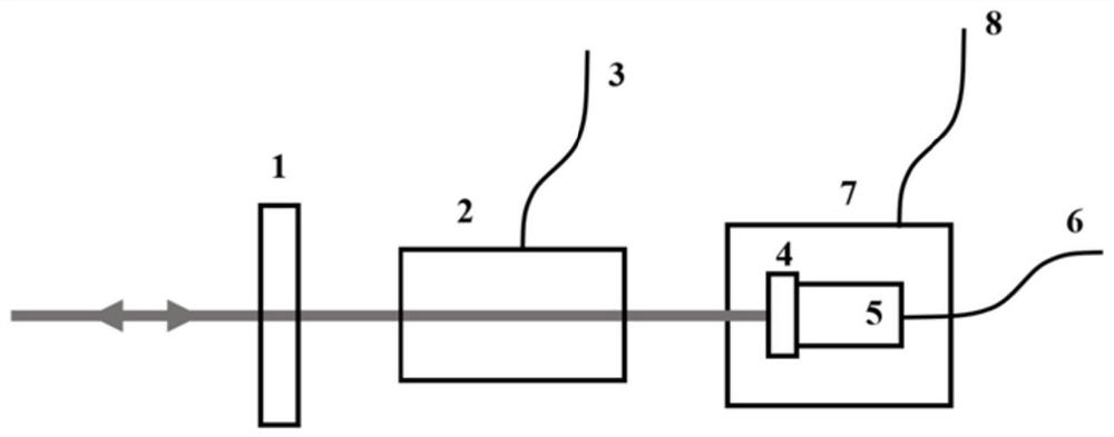
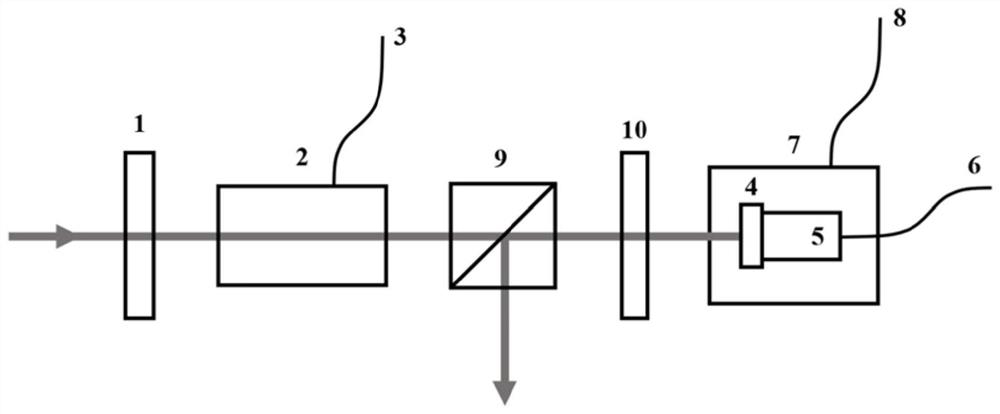
[0035] Among them, the delay compensation system specifically includes a half-wave plate, an electro-optic phase modulator, a total reflection mirror, a piezoelectric ceramic, a stepping motor, and a signal beam splitting conversion module. When the end coincides with the incident end and the polarization direction is the same:

[0036] Half-wave plate: adjust the polarization direction of the incident light pulse signal to be consistent with the crystal optical axis direction of the electro-optic phase modulato...


PUM

PropertyMeasurementUnit
wavelengthaaaaaaaaaa

Abstract

A broadband, high resolution, and large dynamic range delay compensation system and method, using multiple optical path adjustment devices and corresponding multi-layer control mechanisms to effectively connect the range and resolution of different devices, so as to achieve high speed and high resolution The delay compensation mechanism of high rate and large dynamic range effectively relieves the contradiction between the bandwidth, resolution and dynamic range of a single device, and makes full use of the connection relationship between the accuracy and dynamic range coverage and the working bandwidth of different devices. While ensuring wide bandwidth and high resolution, it greatly expands the range of delay compensation, obtains a delay compensation effect that cannot be achieved by a single device, and effectively improves system compatibility.

Description

technical field [0001] The invention relates to a wide-band, high-resolution and large dynamic range delay compensation system and method, belonging to the technical field of lasers. Background technique [0002] In recent years, the highly stable clock distribution technology based on low-noise light sources has gradually become a new research hotspot. Compared with the traditional microwave signal, the femtosecond (fs, 10 -15 s) The ultra-short pulse sequence output by the laser has the characteristics of narrow pulse width, wide spectrum range, and low time jitter. Using it as the carrier of the clock signal can simultaneously realize the precise and lossless transmission of optical frequency signals and radio frequency signals, which is the key to achieving high stability Ideal source for clock distribution. In order to further improve the overall stability of the clock distribution system, it is necessary to further compensate the time noise introduced by various fact...

Claims


Application Information

Patent Timeline
Patent Type & Authority Patents(China)
IPC IPC(8): G02B27/28G02B17/02G02B7/182G02F1/03
CPCG02B27/283G02B27/286G02B17/023G02B7/1821G02F1/03
Inventor 秦鹏王思佳
Owner CHINA ACADEMY OF SPACE TECHNOLOGY
Learn More