
TEC temperature control driving circuit and control strategy thereof

A driving circuit and circuit technology, applied in the direction of temperature control, non-electric variable control, control/regulation system, etc., can solve the problems of output accuracy limitation, large output voltage ripple, occupying large circuit area, etc., and achieve high-precision temperature control , smooth transition, good linearity

Active Publication Date: 2019-09-20
NANJING MOVELASER TECH CO LTD
View PDF24 Cites 5 Cited by
  • Summary
  • Abstract
  • Description
  • Claims
  • Application Information

AI Technical Summary

Problems solved by technology

The H-bridge drive circuit has the following problems: 1. The inductance used is large, the number of components is large, and the circuit area is large.
2. The H-bridge drive circuit is controlled by PWM, the output voltage ripple is large, and the output accuracy is limited by PWM, which is not conducive to achieving higher precision (<0.01°C) temperature control effect
[0007] CN203422694U This patent application utilizes single-channel DC-DC to realize TEC drive, can only heat or cool
CN102519167A This patent application uses a linear voltage regulator module to realize TEC drive, which can only be heated or cooled

Method used


Image

  • TEC temperature control driving circuit and control strategy thereof
  • TEC temperature control driving circuit and control strategy thereof
  • TEC temperature control driving circuit and control strategy thereof

Examples


Embodiment Construction

[0045] The present invention will be further described below in conjunction with embodiment, but protection scope of the present invention is not limited to this:

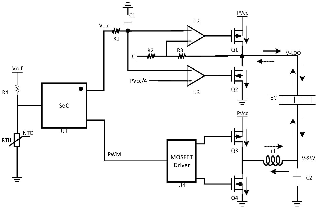
[0046] combine image 3 , a TEC temperature control drive circuit, which includes a main control chip SoC, a linear voltage regulator LDO, a current sink circuit and a switching power supply SW circuit:

[0047]-The main control chip SoC generates the control voltage Vctr of the input terminal of the linear voltage regulator LDO and the current sink circuit, the PWM signal of the input terminal of the switching power supply SW circuit, and detects the voltage feedback value of the thermistor.

[0048] -The output end of the linear voltage regulator LDO is connected to the LDO end of the TEC to provide the input voltage V-LDO, the linear voltage regulator LDO includes the first operational amplifier U2 and the first PMOS transistor Q1 (the adjusting tube in the linear voltage regulator LDO can also be is like Fig...


PUM


Abstract

The invention discloses a TEC temperature control driving circuit which is characterized in that the circuit comprises a linear regulator LDO, a current absorbing circuit and a switching power supply SW circuit. The output end of the linear regulator LDO is connected with the LDO terminal of a TEC to provide input voltage V-LDO. The output end of the switching power supply SW circuit is connected with the SW end of the TEC to provide input voltage V-SW. According to the current absorbing circuit, when V-LDO is greater than V-SW, disconnection is carried out, and current flows from the linear regulator LDO into the TEC; when V-LDO is less than V-SW, breakover is carried out, and current flows from the TEC to the current absorbing circuit. According to the invention, a new LDO+SW topology circuit structure is designed, and the advantages of small LDO ripple and high SW efficiency are combined; the current absorbing circuit is added on the LDO terminal, so that the LDO terminal can output current and absorb current; and the same circuit is used to drive the TEC to carry out heating or refrigeration.

Description

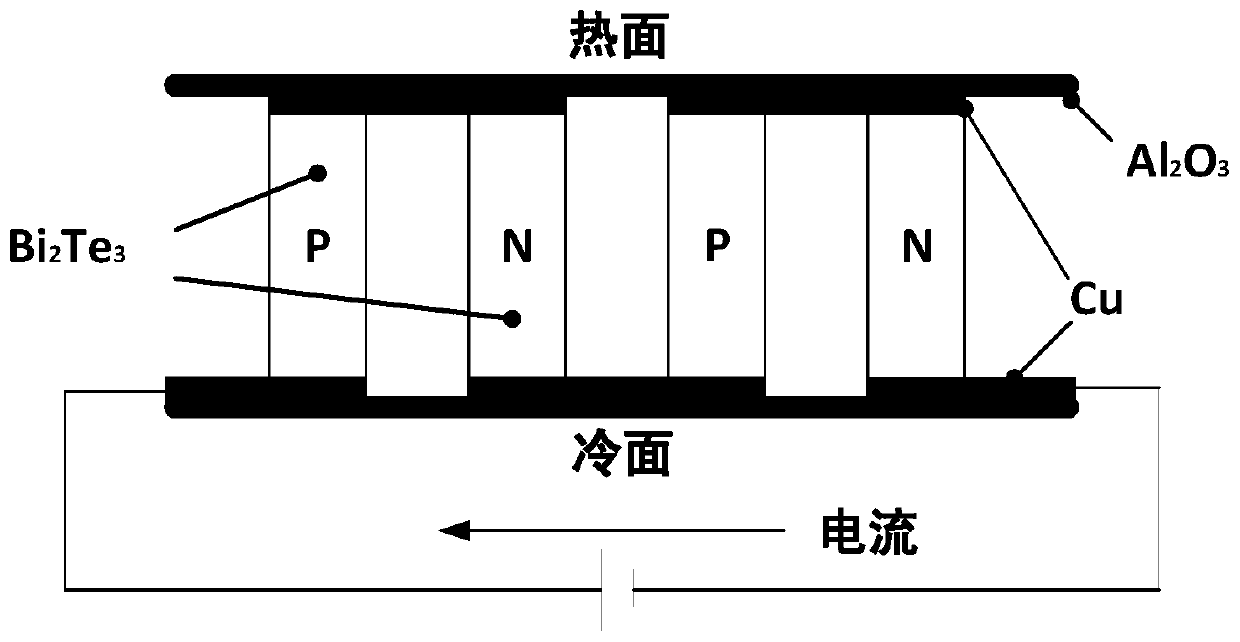
technical field [0001] The invention belongs to the field of drive circuits, in particular to a TEC temperature control drive circuit and a control strategy thereof. Background technique [0002] TEC stands for thermoelectric cooler, such as figure 1 As shown, it is an electronic component based on semiconductor materials. By applying a low DC voltage across the thermoelectric cooler, heat flows from one end of the element to the other. At this time, the temperature at one end of the refrigerator will drop, while the temperature at the other end will rise at the same time. It is worth noting that simply by changing the direction of the current, you can change the direction of the heat flow and send the heat to the other end. Therefore, two functions of cooling and heating can be realized simultaneously on one thermoelectric cooler. Thermoelectric coolers are often used in temperature control circuits, and different drive circuits and control strategies play a crucial rol...

Claims


Application Information

Patent Timeline
Patent Type & Authority Applications(China)
IPC IPC(8): G05D23/24
CPCG05D23/24
Inventor 周健陈帅朱海龙孙杰
Owner NANJING MOVELASER TECH CO LTD
Learn More