
Toxic gas remote monitoring and alarm control system in building

A toxic gas, remote monitoring technology, applied in the field of monitoring and alarm, can solve the safety problems of indoor gas leakage

Inactive Publication Date: 2019-09-20
XI'AN UNIVERSITY OF ARCHITECTURE AND TECHNOLOGY
View PDF8 Cites 7 Cited by
  • Summary
  • Abstract
  • Description
  • Claims
  • Application Information

AI Technical Summary

Problems solved by technology

But what follows is the safety problem caused by indoor gas leakage

Method used


Image

  • Toxic gas remote monitoring and alarm control system in building
  • Toxic gas remote monitoring and alarm control system in building
  • Toxic gas remote monitoring and alarm control system in building

Examples


Embodiment Construction

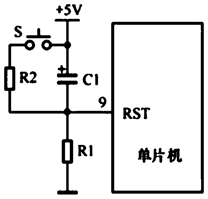
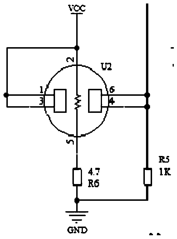
[0039] The present invention will be described in detail below in conjunction with the accompanying drawings.

[0040] It is a control system for remote monitoring and alarming of toxic gases in a building of the present invention, using C language as the programming of the control device STC89C52 single-chip microcomputer, using MQ-7 sensors to monitor the components of toxic gases in the air, and sending them to Executed by a single-chip microcomputer, it can accurately detect the concentration of toxic gases in the room, send out sound and light alarms in time, and send the leak point information to the data management center and personal terminal, and at the same time control the opening of the exhaust fan to reduce the concentration of indoor toxic gases in time.

[0041] like figure 1 Shown is a block diagram of the system hardware structure of the present invention. It mainly includes main control circuit, display circuit, button circuit, sound and light circuit, tempe...


PUM


Abstract

The invention discloses a toxic gas remote monitoring and alarm control system in a building. The system comprises a gas concentration monitoring module used for monitoring various gases in the building, an analog-to-digital conversion module used for quantizing a signal content of the gas concentration monitoring module, a temperature monitoring module used for monitoring a real-time temperature in the building, a button circuit module used for realizing digital input, a main control module used for receiving information of various modules and processing, an LCD display module used for displaying a real-time toxic gas concentration, a real-time indoor temperature and current time, a wireless transmission module used for uploading the temperature in the temperature monitoring module and a monitored value in the gas concentration monitoring module to an upper computer and a personal terminal, a sound and light alarm circuit module used for emitting a sound alarm signal, and a fan exhaust driving module used for inducing and processing information transmitted by the main control module. The system has characteristics of autonomous monitoring and alarm, and automatic exhaust.

Description

technical field [0001] The invention relates to the technical field of monitoring and alarming, in particular to a control system for remote monitoring and alarming of toxic gases in buildings. Background technique [0002] With the continuous development of the industrial level, the air quality is declining year by year, and the air quality in my country is gradually deteriorating. In order to improve the air quality level, my country has gradually paid attention to the development of clean energy, especially the popularization and application of natural gas, combined with the country's vigorous development. With the "West-to-East Gas Pipeline" project, the natural gas industry has a huge room for development in the lives of residents. But what follows is the safety problem caused by indoor gas leakage. [0003] According to the data released by the state, if the volume content of toxic gas leaked in the air of buildings reaches 0.06% of the whole environment, it will cause...

Claims


Application Information

Patent Timeline
Patent Type & Authority Applications(China)
IPC IPC(8): G08B21/14G08C17/02G01D21/02F24F7/007F24F11/70F24F11/89F24F11/58F24F11/88F24F110/10
CPCF24F7/007F24F11/58F24F11/70F24F11/88F24F11/89F24F2110/10G01D21/02G08B21/14G08C17/02
Inventor 罗婵马宗方宋琳高伟
Owner XI'AN UNIVERSITY OF ARCHITECTURE AND TECHNOLOGY
Learn More