Low-cost anisotropic sintered permanent magnetic ferrite radial multi-pole magnetic ring forming mould and method

A permanent magnet ferrite, anisotropic technology, applied in the direction of permanent magnet manufacturing, ceramic molding machines, auxiliary molding equipment, etc., can solve the problems of no involvement, reduce material waste, improve product qualification rate, and improve grinding efficiency Effect

Inactive Publication Date: 2019-09-20
HANGZHOUSNNER MACHINERY EQUIP
View PDF6 Cites 7 Cited by
  • Summary
  • Abstract
  • Description
  • Claims
  • Application Information

AI Technical Summary

Problems solved by technology

Its shortcoming is that this patent only considers a pair of radially oriented permanent magnet ferrite rotors with poles, and does not involve the multi-pair radially oriented permanent magnet ferrite rotors widely used today.
However, this technology only discusses the situation of the permanent magnet ferrite inner rotor, and does not involve the permanent magnet ferrite outer rotor.

Method used


Image

  • Low-cost anisotropic sintered permanent magnetic ferrite radial multi-pole magnetic ring forming mould and method
  • Low-cost anisotropic sintered permanent magnetic ferrite radial multi-pole magnetic ring forming mould and method
  • Low-cost anisotropic sintered permanent magnetic ferrite radial multi-pole magnetic ring forming mould and method

Examples


Embodiment 1

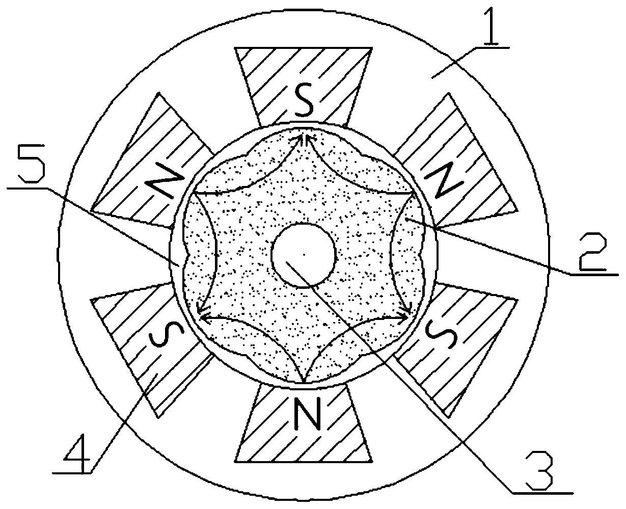
[0032] Example 1: Taking the preparation of an anisotropic sintered permanent ferrite radially oriented hexapole magnetic ring as an example, as figure 1 As shown, the forming mold mainly includes a yoke 1, a ferrite magnetic powder 2, a core rod 3, an NdFeB magnetic block 4, and a mold wall 5. The inner side of the mold wall 5 is used to fill the ferrite magnetic powder 2, and the core rod 3 is set At the center of the inner side of the mold wall, a number of NdFeB magnetic blocks 4 are evenly distributed on the outer circumference of the mold wall 5, and the magnetic poles of two adjacent NdFeB magnetic blocks 4 are set to opposite sexes, and a yoke 1 is set outside the NdFeB magnetic block 4 .

[0033] The number of said NdFeB magnetic blocks 4 is six.

[0034] Adopt the method for above-mentioned forming mold, comprise the following steps:

[0035] 1) Preparation of powder: Take a certain amount of ferrite magnetic powder to prepare the main raw material according to the...

Embodiment 2

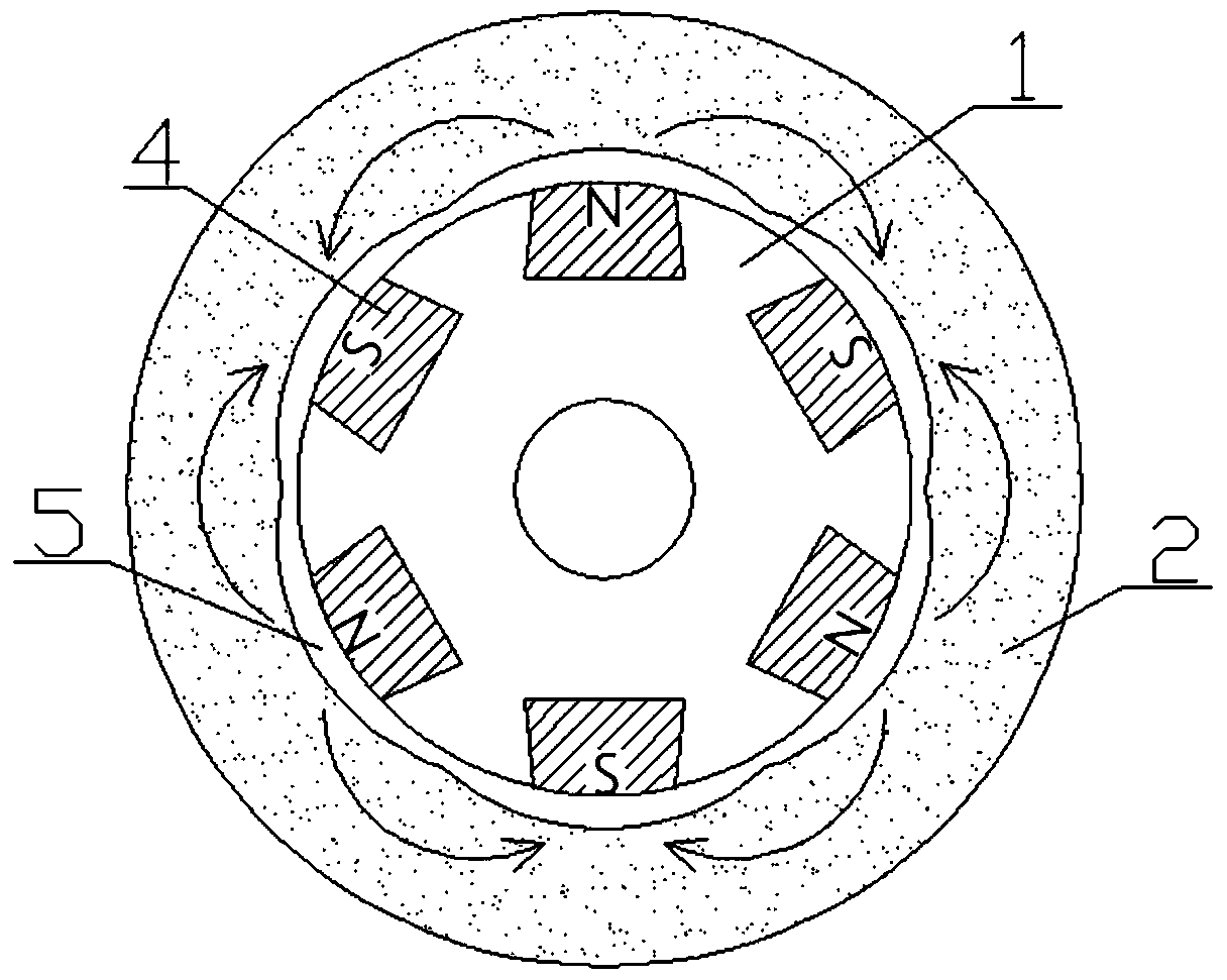
[0041] Example 2: Taking the preparation of an anisotropic sintered permanent ferrite radially oriented hexapole magnetic ring as an example, as figure 2 As shown, the forming mold mainly includes a yoke 1, ferrite magnetic powder 2, NdFeB magnetic block 4, and mold wall 5. The outer side of the mold wall 5 is used to fill the ferrite magnetic powder 2, and the inner circumference of the mold wall 5 is evenly distributed. NdFeB magnetic blocks 4, and the magnetic poles of two adjacent NdFeB magnetic blocks 4 are set to opposite sexes, and the inner side of the NdFeB magnetic blocks 4 is provided with a yoke 1.

[0042] The number of said NdFeB magnetic blocks 4 is six.

[0043] Adopt the method for above-mentioned forming mold, comprise the following steps:

[0044] 1) Preparation of powder: Take a certain amount of ferrite magnetic powder to prepare the main raw material according to the predetermined formula, add additives once to wet-mill the mixture, and pre-sinter the s...


PUM


Abstract

The invention discloses a low-cost anisotropic sintered permanent magnetic ferrite radial multi-pole magnetic ring near-net forming mould and a method. The forming mould mainly comprises magnetic yokes, ferrite magnetic powder, a core rod, neodymium-iron-boron magnetic blocks, and a mould wall; the inner side of the mould wall is filled with the ferrite magnetic powder; the core rod is arranged in the center of the inner side of the mould wall; the neodymium-iron-boron magnetic blocks are uniformly distributed on the circumference of the outer side of the mould wall; and the magnetic yokes are arranged on the outer sides of the neodymium-iron-boron magnetic blocks. The forming mould considering the difference of the shrinkage rates of one circle of a magnetic ring is adopted, so that the working surface side of the sintered blank magnetic ring has good cylindricity; the high-performance neodymium-iron-boron permanent magnetic blocks are adopted as orientation clamp magnetic field generation sources, so that the magnetic field is stable, and the orientation of the poles of the ferrite magnetic ring is ensured to be uniform; the advantages are more obvious in preparation of a series of products such as radial two-pole, four-pole, six-pole, eight-pole and ten-pole products and the like; and the forming mould is suitable for outer circular anisotropic radial multi-pole magnetic rings and inner circular anisotropic radial multi-pole magnetic rings, and has high universality.

Description

technical field [0001] The invention relates to the field of manufacturing sintered permanent magnet ferrite materials, in particular to a low-cost anisotropic sintered permanent magnet ferrite radially oriented multi-pole magnetic ring near-net shape mold and method. Background technique [0002] Anisotropic sintered permanent magnet ferrite radially oriented multi-pole magnetic ring is a branch of sintered permanent magnet ferrite material. Due to its special orientation, the surface magnetic field strength of the magnetic ring is in a periodic approximate sinusoidal wave state around the central axis of rotation. distributed. In view of the above characteristics, sintered permanent ferrite radially oriented multi-pole magnetic rings are widely used in the fields of micro-motors, microwave devices, magnetic transmission, sensors, instruments and meters. Generally speaking, in the magnetic field orientation forming stage of anisotropic sintered permanent magnet ferrite rad...

Claims


Application Information

Patent Timeline
Patent Type & Authority Applications(China)
IPC IPC(8): H01F41/02B28B7/42B28B17/02
CPCB28B7/42B28B17/02H01F41/0253H01F41/0266H01F41/028
Inventor 柴晓峰吕欢剑郭强章华群
Owner HANGZHOUSNNER MACHINERY EQUIP
Why Eureka
Try Eureka