
NB-IOT-based micro-grid information acquisition and monitoring system and implementation method thereof

A monitoring system and information collection technology, applied in information technology support systems, transmission systems, electrical components, etc., can solve the problems of high cost, micro-grid equipment loss, and high power consumption of GPRS modules wireless transmission modules, to extend life, reduce The effect of accidental loss

Pending Publication Date: 2019-09-20
SHANGHAI UNIV
View PDF4 Cites 5 Cited by
  • Summary
  • Abstract
  • Description
  • Claims
  • Application Information

AI Technical Summary

Problems solved by technology

[0003] At this stage, most of the communication networks of microgrids are composed of fieldbus networks including MODBUS, PROFIBUS, CAN, etc. Such fieldbus microgrid systems have the problems of data islands, poor scalability, and lack of remote monitoring functions; and a small number of microgrids The communication network of the power grid system is composed of a GPRS network, but the GPRS module has the problems of high power consumption, poor signal, high cost, and relatively short life of the wireless transmission module, which leads to obvious defects in the microgrid system composed of it.
[0004] In extreme weather conditions, the on-site equipment of the micro-grid often suffers from loss or even damage. In order to reduce the occurrence of such situations, it is urgent to closely monitor the working environment of the on-site equipment of the micro-grid.

Method used


Image

  • NB-IOT-based micro-grid information acquisition and monitoring system and implementation method thereof
  • NB-IOT-based micro-grid information acquisition and monitoring system and implementation method thereof
  • NB-IOT-based micro-grid information acquisition and monitoring system and implementation method thereof

Examples


Embodiment Construction

[0037] In order to make the technical solutions and advantages of the present invention clearer, the following preferred embodiments will be further described in detail in conjunction with the accompanying drawings.

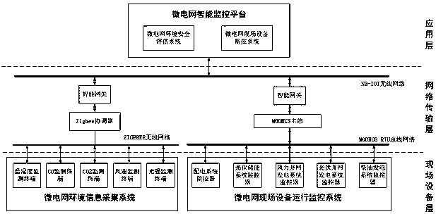
[0038] Such as figure 1 As shown, a microgrid information collection and monitoring system based on NB-IOT, including field device layer, network transmission layer and platform application layer;

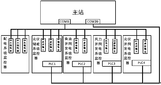
[0039] The field equipment layer includes a microgrid environmental information collection system and a microgrid field equipment operation monitoring system; the microgrid environmental information collection system includes a temperature and humidity monitoring terminal, a carbon monoxide content monitoring terminal, a carbon dioxide content monitoring terminal, a wind speed monitoring terminal and an optical The strong monitoring terminal is responsible for collecting the environmental data of the micro-grid site; the micro-grid site equipment operation monitoring...


PUM


Abstract

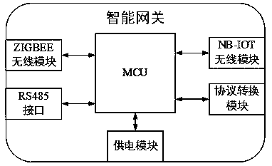
The invention relates to an NB-IOT-based micro-grid information acquisition and monitoring system and an implementation method thereof. The system comprises a field equipment layer, a network transmission layer and an application layer. The field equipment layer comprises a micro-grid environment information acquisition system and a micro-grid field equipment monitoring system, and is responsible for collecting environment data and field equipment operation data; the network transmission layer comprises a ZIGBEE wireless network, a MODBUS RTU bus network, an intelligent gateway and an NB-IOT network, and is responsible for data transmission and protocol conversion; the application layer comprises a micro-grid intelligent monitoring platform; and the micro-grid intelligent monitoring platform comprises a micro-grid environment safety evaluation system and a micro-grid field equipment monitoring system, and provides system monitoring and environment evaluation functions. The intelligent gateway is added into a traditional micro-grid, and remote transmission of micro-grid system data is realized through a protocol converter embedded in the gateway, so that remote monitoring of the system is realized; and by means of the micro-grid environment safety evaluation system, the possibility of accidental loss of field equipment is reduced.

Description

technical field [0001] The invention relates to the field of microgrid and Internet of Things development, in particular to an NB-IOT-based microgrid information collection and monitoring system and an implementation method thereof. Background technique [0002] Microgrid refers to a small power generation and distribution system composed of distributed power sources, energy storage devices, energy conversion devices, loads, monitoring and protection devices, etc. The proposal of microgrid aims to realize the flexible and efficient application of distributed power, and solve the problem of grid connection of distributed power with a large number and various forms. The development and extension of microgrids can fully promote the large-scale access of distributed power sources and renewable energy, and realize the highly reliable supply of various energy forms for loads. Smart grid transition. [0003] At this stage, most of the communication networks of microgrids are comp...

Claims


Application Information

Patent Timeline
IPC IPC(8): H02J13/00H04L29/06H04L29/08
CPCH02J13/0062H02J13/0075H04L67/12H04L69/08H04L69/22Y04S40/126Y04S40/128Y02B90/20Y02E60/00
Inventor 杜大军徐智劼张圳圳张云鹏蔡佳浩彭晨
Owner SHANGHAI UNIV
Learn More