Mixing device for producing high-performance permanent magnetic ferrite material

A permanent magnet ferrite and mixing device technology, which is applied to mixers with rotating stirring devices, mixers, transportation and packaging, etc., can solve problems such as large motor loads

Pending Publication Date: 2019-09-24
ANHUI HONGTAI ELECTROMAGNETIC
View PDF0 Cites 2 Cited by
  • Summary
  • Abstract
  • Description
  • Claims
  • Application Information

AI Technical Summary

Problems solved by technology

[0005] Aiming at the problems in the prior art, the purpose of the present invention is to provide a mixing device for producing high-performance permanent magnet ferrite materials, which solves the technical problem of heavy load when the motor is started

Method used


Image

  • Mixing device for producing high-performance permanent magnetic ferrite material
  • Mixing device for producing high-performance permanent magnetic ferrite material
  • Mixing device for producing high-performance permanent magnetic ferrite material

Examples


Embodiment 1

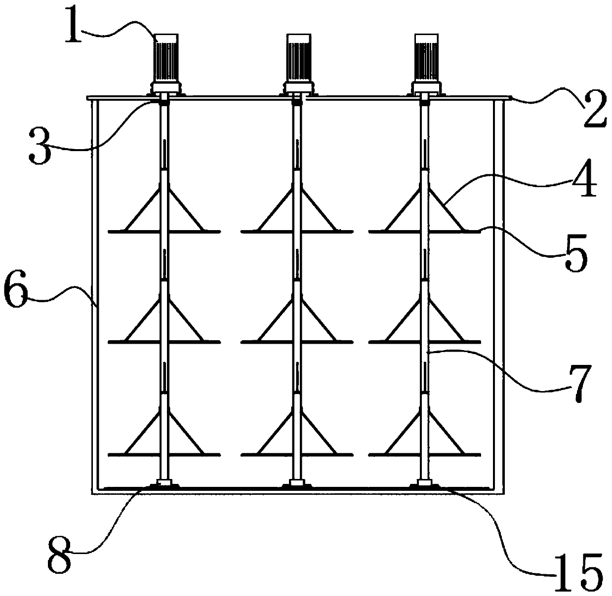
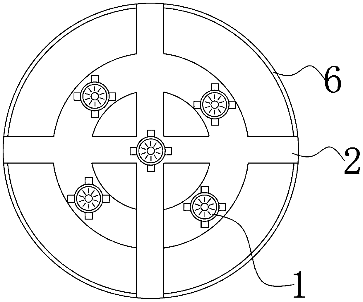
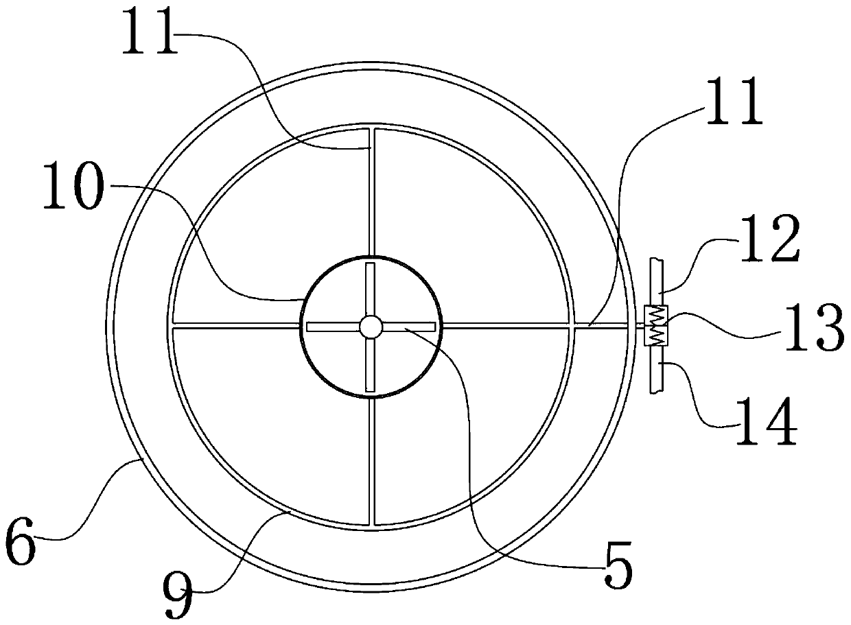
[0021] see Figure 1-4 , is a schematic diagram of the overall structure in one embodiment; it includes a mixing cylinder 6 made of cement and stones, a support frame 2 is built on the top of the mixing cylinder 6, and a motor 1 is installed on the top of the support frame 2, and the motor 1 has a total There are multiple, each motor 1 is connected to an independent shaft 7 at the bottom, the outer wall of each shaft 7 is provided with a stirring claw 5, and the bottom end of each shaft 7 is fixed on the base 8, There are a plurality of bases 8, and the bases 8 are evenly distributed on the bottom of the mixing cylinder 6, so that each stirring claw is driven by an independent motor, so that when the stirring claws start stirring, the force arm is shorter and the torque is smaller. When the stirring claws are stirred in the mixing barrel, the resistance of the material to the stirring claws is small. The bottom plate of the mixing barrel 6 has a pipe 15 to avoid material sedim...

Embodiment 2

[0024] see Figure 1-4 , is a schematic diagram of the overall structure in one embodiment; it includes a mixing cylinder 6 made of cement and stones, a support frame 2 is built on the top of the mixing cylinder 6, and a motor 1 is installed on the top of the support frame 2, and the motor 1 has a total There are multiple, each motor 1 is connected to an independent shaft 7 at the bottom, the outer wall of each shaft 7 is provided with a stirring claw 5, and the bottom end of each shaft 7 is fixed on the base 8, There are a plurality of bases 8, and the bases 8 are evenly distributed on the bottom of the mixing cylinder 6, so that each stirring claw is driven by an independent motor, so that when the stirring claws start stirring, the force arm is shorter and the torque is smaller. When the stirring claws are stirred in the mixing barrel, the resistance of the material to the stirring claws is small. The bottom plate of the mixing barrel 6 has a pipe 15 to avoid material sedim...

Embodiment 3

[0029] see Figure 1-4 , is a schematic diagram of the overall structure in one embodiment; it includes a mixing cylinder 6 made of cement and stones, a support frame 2 is built on the top of the mixing cylinder 6, and a motor 1 is installed on the top of the support frame 2, and the motor 1 has a total There are multiple, each motor 1 is connected to an independent shaft 7 at the bottom, the outer wall of each shaft 7 is provided with a stirring claw 5, and the bottom end of each shaft 7 is fixed on the base 8, There are a plurality of bases 8, and the bases 8 are evenly distributed on the bottom of the mixing cylinder 6, so that each stirring claw is driven by an independent motor, so that when the stirring claws start stirring, the force arm is shorter and the torque is smaller. When the stirring claws are stirred in the mixing barrel, the resistance of the material to the stirring claws is small. The bottom plate of the mixing barrel 6 has a pipe 15 to avoid material sedim...


PUM


Abstract

The invention discloses a mixing device for producing a high-performance permanent magnetic ferrite material, and relates to the technical field of magnetic material production equipment. The mixing device for producing the high-performance permanent magnetic ferrite material comprises a mixing cylinder which is built of a mixture of cement and pebbles, a supporting rack is set up on the top of the mixing cylinder, multiple motors are installed on the top of the supporting rack, and an independent shaft lever is connected with the bottom of each motor. According to the mixing device for producing the high-performance permanent magnetic ferrite material, multiple stirring claws are arranged in the mixing cylinder, each stirring claw is driven by one corresponding independent motor, thus when the stirring claws conduct stirring, force arms are short, torque is low, when the stirring claws conduct stirring in the mixing cylinder, resistance of a material to the stirring claws is low, and in order to prevent the situation that in a stirring process, the material precipitates on the bottom of the mixing cylinder, coils used for spraying water or gas to the bottom of the mixing cylinder are arranged on the bottom of the mixing cylinder in a coiled mode, so that precipitation of the material is avoided, and the evenness of the material stirred in the mixing cylinder is improved.

Description

Technical field: [0001] The invention relates to the technical field of magnetic material production equipment, in particular to a mixing device for producing high-performance permanent magnet ferrite materials. Background technique: [0002] Ferrite is a new type of non-metallic magnetic material developed in the 1940s. It is sometimes called magnetic porcelain because of its preparation process and appearance similar to ceramics. Ferrite generally refers to the composite oxide of iron group and one or more other appropriate metal elements, which belongs to semiconductor and is used as a magnetic medium. [0003] Magnetite, the main component of which is Fe 3 o 4 , is the simplest ferrite, and is also the earliest non-metallic magnetic material used by humans. A composite oxide composed of iron oxide and one or several other metal oxides (such as BaO·6Fe 2 o 3 , MnO·Fe 2 o 3 ·ZnO·Fe 2 o 3 etc.) are called ferrites. [0004] In the process of ferrite production, i...

Claims


Application Information

Patent Timeline
Patent Type & Authority Applications(China)
IPC IPC(8): B01F7/20B01F27/906
CPCB01F27/906B01F27/85
Inventor 余涛余兴如余超宋加培陈号
Owner ANHUI HONGTAI ELECTROMAGNETIC
Why Eureka
Try Eureka