Power station boiler membrane type water-cooled wall cleaning device

A membrane-type water-cooled wall and cleaning device technology, which is applied to the removal of solid residues, treatment of combustion products, and combustion methods, can solve problems such as small structural stress, large changes in boiler heat load, and difficult handling of the top of the boiler. The effect of clear image and simple operation

Pending Publication Date: 2019-09-24
江阴德耐特重工科技有限公司
View PDF0 Cites 0 Cited by
  • Summary
  • Abstract
  • Description
  • Claims
  • Application Information

AI Technical Summary

Problems solved by technology

[0003] However, there are certain safety problems in the existing membrane-type water-cooled walls of boilers. The thermal load of the boilers varies greatly. The thermal stress in the circumferential direction of the tube is uniform, the circumferential thickness of the tube is equal, the structure does not change, the structural stress is small, and its service life in normal operation can reach more than 20 to 30 years, while the membrane wall (finned tube) is a smooth tube. Composed of welded flat steel, after one side of the furnace is subjected to radiation heat exchange, the temperature along the circumference of the pipe is as follows: Figure 17 shown, from the attached Figure 17 It can be seen from the figure that after the membrane wall tube is radiated and heat-exchanged in the furnace, the temperature gradient along the circumference of the tube is very large, generally reaching about 2 times. If the upper inner wall is f

Method used


Image

  • Power station boiler membrane type water-cooled wall cleaning device
  • Power station boiler membrane type water-cooled wall cleaning device
  • Power station boiler membrane type water-cooled wall cleaning device

Examples


Example Embodiment

[0039] Embodiment one

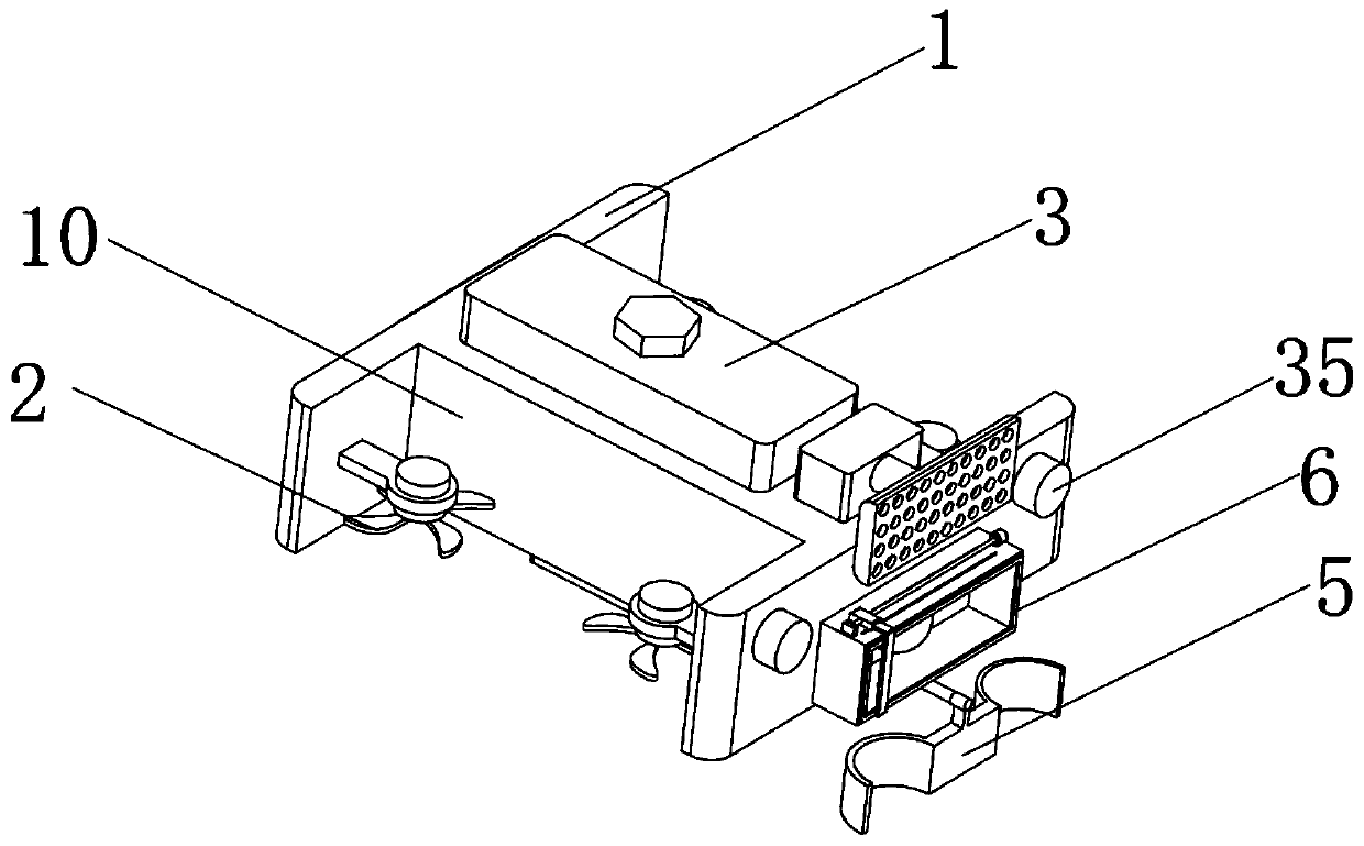
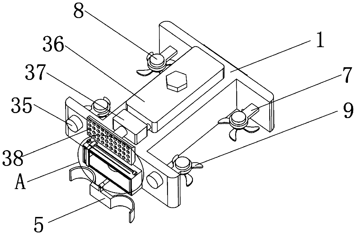
[0040] see Figure 1-12 , the present invention provides a technical solution: a power plant boiler membrane water wall cleaning device, including a housing 1, the two sides of the housing 1 are equipped with wing devices 2, and the top of the housing 1 is fixed with a sprinkler 3. The bottom of the housing 1 is provided with a drive device 4, the output end of the drive device 4 is movably connected to the ash removal mechanism 5, and the side of the housing 1 close to the ash removal mechanism 5 is fixed with a camera mechanism 6.

[0041] The wing device 2 includes a support frame 7, a first micro-motor 8 and a rotating blade 9, and a U-shaped through hole 10 is opened on both sides of the housing 1, and the support frame 7 is fixed on the U-shaped through hole 10 On the wall of the hole, the rotating vane 9 is fixed on the output end of the first micro motor 8 .

[0042] Working principle: The output end of the first micro-motor 8 drives the rota...

Example Embodiment

[0051] Embodiment two

[0052] see Figure 13-16 , here is different from Embodiment 1, because the cleaning part 21 is movably connected on the connecting rod 20, so the cleaning part 21 can be disassembled from the connecting rod 20, and the connecting rod 20 moves away from the end of the fixed block 14 A welding device 47 is provided;

[0053] The welding device 47 includes a welding shell 48, a fixed plate 49, a heating wire 50 and a clamping device 51, the fixed plate 49 is fixed inside the re-welding shell 48, and the end of the connecting rod 20 away from the fixed block 14 is provided with a Circular groove 52, one end of the heating wire 50 is set in the circular groove 52, and the other end of the heating wire 50 passes through the fixed plate 49 and is connected to one end inside the welding shell 48, and the clamping device 51 is provided On the welding shell 48 and on the surface of the connecting rod 20 is provided a locking groove 53 , and the welding shell 4...


PUM


Abstract

The invention discloses a power station boiler membrane type water-cooled wall cleaning device. The power station boiler membrane type water-cooled wall cleaning device comprises a shell, wing devices are arranged on the two sides of the shell, a water spraying device is fixed at the top of the shell, a driving device is arranged at the bottom of the shell, a dust removing mechanism is movably connected to the output end of the driving device, and a camera shooting mechanism is fixed on the side, close to the dust removing mechanism, of the shell. According to the power station boiler membrane type water-cooled wall cleaning device, the effect that people do not need to enter a boiler to perform dust removing treatment on the membrane type water-cooled wall inside the boiler can be achieved, moreover, through the power station boiler membrane type water-cooled wall cleaning device, the membrane type water-cooled wall inside the boiler can undergo full-aspect dust removing treatment, the operation is relatively simple, and the certain efficiency is achieved.

Description

technical field [0001] The invention relates to the technical field of membrane water-cooled wall cleaning, in particular to a membrane-type water-cooled wall cleaning device for power plant boilers. Background technique [0002] From the perspective of boiler development history, the water-cooled wall of the drum boiler below the subcritical pressure is to protect the furnace wall, reduce its temperature, and improve the operational reliability of the boiler. Today, it has become the main evaporation heating surface of the boiler, and the water-cooled wall Placed on the inner wall of the furnace, close to the furnace wall and continuously lined up, basically in a vertical arrangement, generally composed of bare tubes or finned tubes, the main functions of the water wall are to protect the furnace wall, reduce coal slag and The high temperature of radiation has a destructive effect on the furnace wall. At present, the radiation heat transfer of the flame to the water wall ha...

Claims


Application Information

Patent Timeline
IPC IPC(8): F23M5/08F23J3/00
CPCF23J3/00F23M5/08
Inventor 李俊陈金龙黄岳军谭梦磊谭海江赵虎赵文涛糜晓航
Owner 江阴德耐特重工科技有限公司
Why Eureka
Try Eureka