Eureka AIR delivers breakthrough ideas for toughest innovation challenges, trusted by R&D personnel around the world.

Tube pass tandem type tube and shell heat exchanger based on deep sea self-flow circulation cooling system

A technology of circulating cooling system and shell-and-tube heat exchanger, applied in the direction of heat exchanger type, heat exchanger shell, indirect heat exchanger, etc., can solve the problem of occupying outboard space and increasing seawater resistance loss on the tube side. It can ensure the heat exchange function and sealing reliability, reduce the resistance along the seawater side, and achieve the effect of simple structure.

Inactive Publication Date: 2019-09-24
CHINA SHIP SCIENTIFIC RESEARCH CENTER (THE 702 INSTITUTE OF CHINA SHIPBUILDING INDUSTRY CORPORATION)
View PDF6 Cites 4 Cited by
  • Summary
  • Abstract
  • Description
  • Claims
  • Application Information

AI Technical Summary

Problems solved by technology

In order to meet the requirements of backup and safety, the existing solution is to connect two independent heat exchangers in series or in parallel, but there are multiple tube boxes in both forms, which increases the resistance loss of seawater in the tube side
And subject to the limited side space, the parallel connection requires two sets of piping systems, which will take up too much space outside the side

Method used


Image

  • Tube pass tandem type tube and shell heat exchanger based on deep sea self-flow circulation cooling system
  • Tube pass tandem type tube and shell heat exchanger based on deep sea self-flow circulation cooling system

Examples


Embodiment Construction

[0018] Specific embodiments of the present invention will be described below.

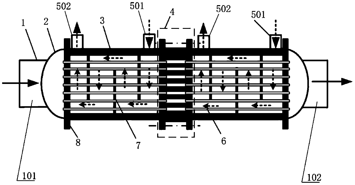
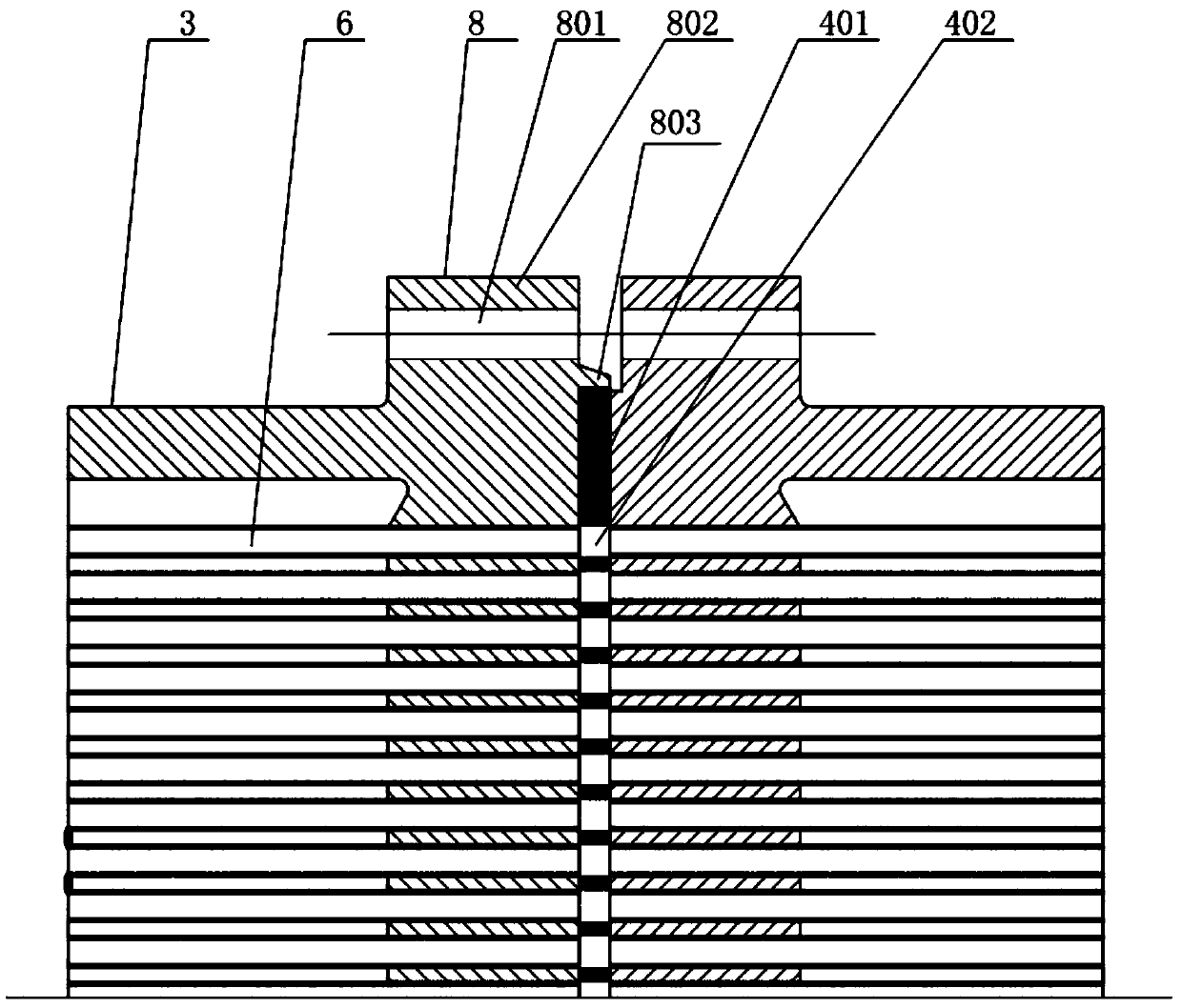
[0019] Such as figure 1 As shown, the tube-side serial shell-and-tube heat exchanger used in the deep-sea artesian circulating cooling system includes a shell 3 with a fresh water inlet pipe 501 and a fresh water outlet pipe 502, a heat exchange tube 6, a baffle plate 7 and a tube sheet 8. The tube sheets 8 are respectively installed at both ends of the casing 3, and a plurality of baffles 7 arranged at intervals are arranged radially inside the casing 3, and each tube sheet 8 and the baffles 7 are provided with Mounting holes, a plurality of heat exchange tubes 6 radially penetrate the mounting holes of the baffle plate 7 and are respectively connected with the tube sheets 8 at both ends of the shell 3. In the present invention, the heat exchange tubes 6 and the tube sheets 8 are connected by expansion welding and way to ensure sealing. It also includes a water collection chamber 2. The water co...


PUM


Abstract

The invention relates to a tube pass tandem type tube and shell heat exchanger based on a deep sea self-flow circulation cooling system. The tube pass tandem type tube and shell heat exchanger comprises a shell body, heat exchange tubes, baffle plates and tube plates. The tube plates are mounted at the two ends of the shell body separately, the multiple baffle plates are arranged in the shell body in the radial direction, mounting holes are formed in the tube plates and the baffle plates, and the multiple heat exchange tubes penetrate through the mounting holes of the baffle plates and are connected with the tube plates at the two ends of the shell body separately. The tube pass tandem type tube and shell heat exchanger further comprises water collecting chambers. The water collecting chambers are arranged on the outer sides of any tube plates. The water collecting chambers, the shell body, the heat exchange tubes, the baffle plates and the tube plates are combined to form sub heat exchangers, the adjacent sub heat exchangers are connected in series through barrel body connecting devices, and tube passes between the adjacent sub heat exchangers are connected into a whole. Sea water directly flows through the tube passes, so that the resistance loss of the sea water along the passes is reduced, the critical flow velocity point of self-flow circulation is reduced, and the self-flow circulation capacity is improved. The sub heat exchangers are connected in series through the barrel body connecting devices, and therefore the heat exchange function and the sealing reliability of the sub heat exchangers can be guaranteed.

Description

technical field [0001] The invention relates to the field, in particular to a tube-side serial shell-and-tube heat exchanger used in a deep-sea artesian circulation cooling system. Background technique [0002] As the core heat exchange component of the deep sea artesian circulation cooling system, the heat exchanger is different from the conventional land heat exchanger. Arranging the heat exchanger outboard is beneficial to its heat exchange and will inevitably make the heat exchanger withstand high seawater pressure. [0003] The application of the self-flowing circulation system puts forward higher requirements on the seawater side resistance loss of the heat exchanger. While meeting the heat exchange requirements, the heat exchanger must be designed with low seawater flow resistance in the tube side. The traditional heat exchanger is a single structure, and the heat exchange tube or pressure shell may leak under high pressure. As deep-sea equipment, the environment us...

Claims


Application Information

Patent Timeline
IPC IPC(8): F28D7/16F28F9/26
CPCF28D7/1607F28F9/26F28F2275/20
Inventor 陈康张万良仝潘夏彬马向能
Owner CHINA SHIP SCIENTIFIC RESEARCH CENTER (THE 702 INSTITUTE OF CHINA SHIPBUILDING INDUSTRY CORPORATION)
Why Eureka
Eureka Blog
Learn More