Wavelength division multiplexer

A wavelength division multiplexer and filter technology, which is applied in the direction of instruments, light guides, optics, etc., can solve the problems of complex manufacturing, low production efficiency, and difficult adjustment of wavelength division multiplexers, and achieve the best light propagation angle and structure The effect of simple, simplified structure settings

Pending Publication Date: 2019-09-24
A-ONE TECH LTD
View PDF0 Cites 2 Cited by
  • Summary
  • Abstract
  • Description
  • Claims
  • Application Information

AI Technical Summary

Problems solved by technology

When making the existing wavelength division multiplexer, it is necessary to assemble the pigtail and the angle and spacing of the double-fiber pigtail 2, lens 3, filter 4, lens 5 and single-wire pigtail 6, because all devices need to be installed in the casing 4, the space is narrow, and it is more difficult to adjust, which makes the production of the wavelength division multiplexer more complicated and the production efficiency is lower

Method used


Image

  • Wavelength division multiplexer
  • Wavelength division multiplexer
  • Wavelength division multiplexer

Examples


Embodiment Construction

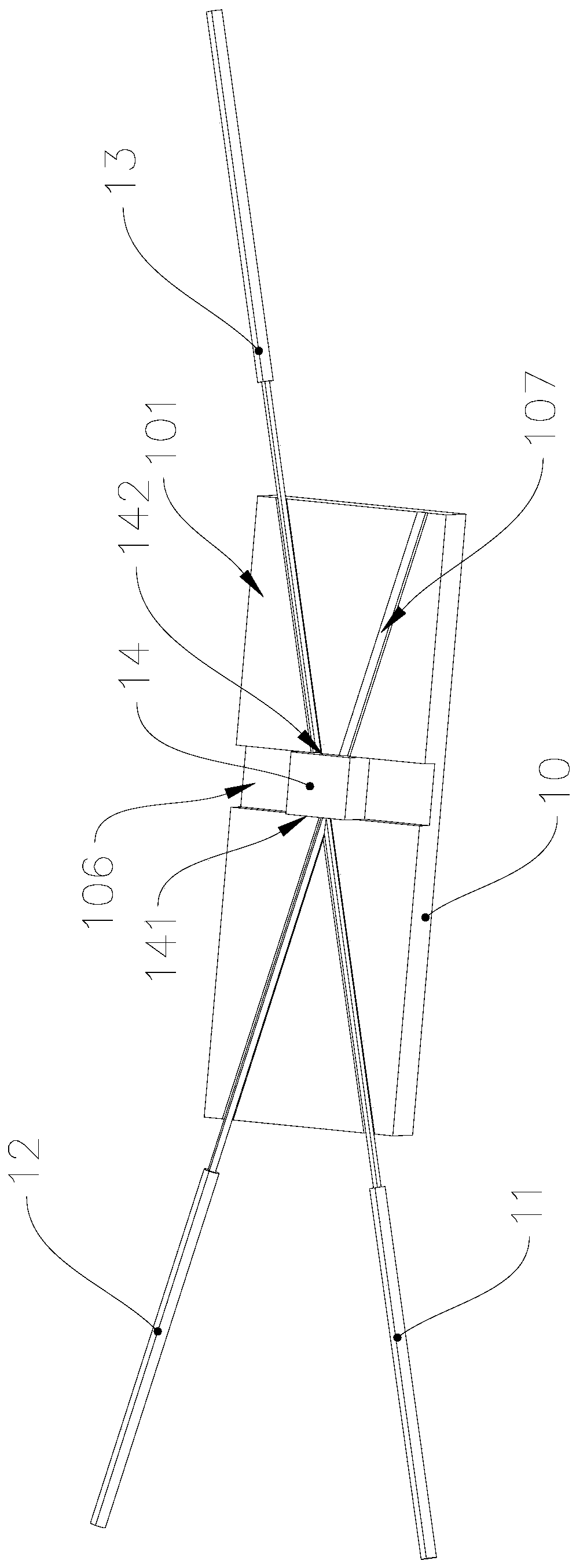
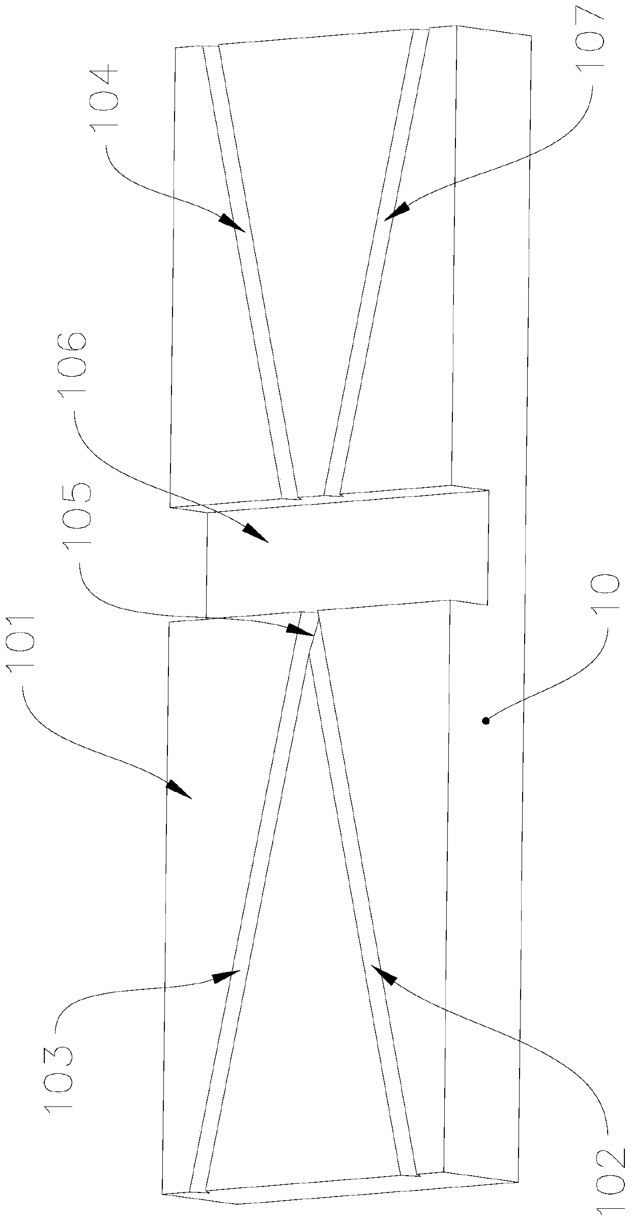
[0022] Such as figure 2 As shown, the wavelength division multiplexer of this embodiment includes a substrate 10 , an optical fiber 11 at an incident end, an optical fiber 12 at a reflection end, an optical fiber 13 at a passing end, and a filter 14 , wherein the substrate 10 is a glass substrate. see image 3 , the first side wall 101 of the substrate 10 is provided with an incident end groove 102, a reflective end groove 103 and a passing end groove 104, the incident end groove 102 and the reflecting end groove 103 intersect at a preset angle, and the passing end groove The groove 104 is arranged coaxially with the groove 102 at the incident end, preferably, the preset angle is 60 degrees. The filter 14 is installed at the junction 105 of the incident end groove 102 and the reflective end groove 103, the incident end optical fiber 11 is installed in the incident end groove 102, the reflective end optical fiber 12 is installed in the reflective end groove 103, and the passi...


PUM


Abstract

The invention provides a wavelength division multiplexer. The wavelength division multiplexer comprises a substrate, an incident end optical fiber, a reflecting end optical fiber, a passing end optical fiber and a filtering sheet; an incident end groove, a reflecting end groove and a passing end groove are formed in the first side wall of the substrate; the incident end groove and the reflecting end groove are arranged at a preset angle in an intersecting manner; the passing end groove and the incident end groove are coaxially arranged; the filtering sheet is installed at the intersection of the incident end groove and the reflecting end groove; the incident end optical fiber is installed in the incident end groove; the reflecting end optical fiber is installed in the reflecting end groove; the passing end optical fiber is installed in the passing end groove; the end surface of the incident end of the incident end optical fiber, which is located at the intersection, is parallel to the first plane of the filtering sheet, wherein the first plane faces the intersection; the end surface of the reflecting end of the reflecting end optical fiber is parallel to the first plane; and the end surface of the passing end of the passing end optical fiber is parallel to the second plane of the filtering sheet, wherein the second plane faces the passing end groove. The wavelength division multiplexer of the invention has the advantages of structural simplicity and convenience in assembly.

Description

technical field [0001] The invention relates to the technical field of wavelength division multiplexers, in particular to a wavelength division multiplexer. Background technique [0002] In an optical communication system, a wavelength division multiplexer (Wavelength Division Multiplexer, WDM) is used to combine or decompose optical signals of different wavelengths. With the development of optical communication technology, the wavelength division multiplexer is more and more widely used. Such as figure 1 As shown, the existing wavelength division multiplexer usually includes a sleeve 1, a dual-fiber pigtail 2, a lens 3, a filter 4, a lens 5 and a single-wire pigtail 6, a dual-fiber pigtail 2, a lens 3, a filter 4, The lens 5 and the single-wire pigtail 6 are installed in the casing 1 in a predetermined arrangement. When the existing wavelength division multiplexer is manufactured, it is necessary to assemble the pigtail and the angle and spacing of the double-fiber pigtai...

Claims


Application Information

Patent Timeline
Patent Type & Authority Applications(China)
IPC IPC(8): G02B6/293G02B6/44
CPCG02B6/293G02B6/44
Inventor 朴木孝旭史向东黄永兴汤远亮唐梦真
Owner A-ONE TECH LTD
Why Eureka
Try Eureka