Gasifier burner structure with spiral flow channel

A technology of spiral flow channel and gasifier, which is applied in the details of gasification devices, granular/powdered fuel gasification, petroleum industry, etc., and can solve the problems of obstructing the passage of fuel and high-pressure oxygen, frequent maintenance, maintenance or replacement of burners, etc. Furnace cooling and other issues to achieve the effect of reducing the probability of mechanical failure, reducing the risk of cracking, and improving heat exchange efficiency

Pending Publication Date: 2019-09-27
NANJING ZHUANLU TECH
View PDF0 Cites 0 Cited by
  • Summary
  • Abstract
  • Description
  • Claims
  • Application Information

AI Technical Summary

Problems solved by technology

[0004] 1. The rigidity of the burner is not enough, because the three-layer nested flow channels are only welded by a few support plates, and the fluid will vibrate when passing through the flow channels. When high-pressure oxygen and coal-water slurry flow at high speed in the three-layer flow channels, Vibrations of different frequencies will be generated, and the vibration will have a continuous impact on the support plate between the flow channels, resulting in cracks in the weld between the support plate and the flow channel;
[0005] 2. The mixing of coal water slurry and oxygen is not enough, the flow direction of coal water slurry and high pressure oxygen is the same, especially when working under low load conditions, the injection speed of coal water slurry and oxygen is insufficient, it is difficult to fully mix the mist It cannot be fully burned, which reduces the combustion efficiency;
[0006] 3. The structure of the burner is complex, and the nested structure of the three-layer flow channel makes the coal-water slurry easy to form carbon deposits in the narrow gaps.
Carbon deposits will form adhesions between flow channels, which not only hinder the passage of fuel and high-pressure oxygen, but also hinder the disassembly and cleaning of the burner during maintenance
[0007] 4. The cooling water pipe is external and spirally wound on the burner, which is also prone to carbon deposits, making disassembly difficult
[0008] To sum up, the existing burner structure of the gasifier has a short service life and frequent maintenance, and the maintenance or replacement of the burner needs to be shut down for cooling, resulting in a huge impact on the entire production process and large economic losses. Improve

Method used


Image

  • Gasifier burner structure with spiral flow channel
  • Gasifier burner structure with spiral flow channel
  • Gasifier burner structure with spiral flow channel

Examples


Embodiment Construction

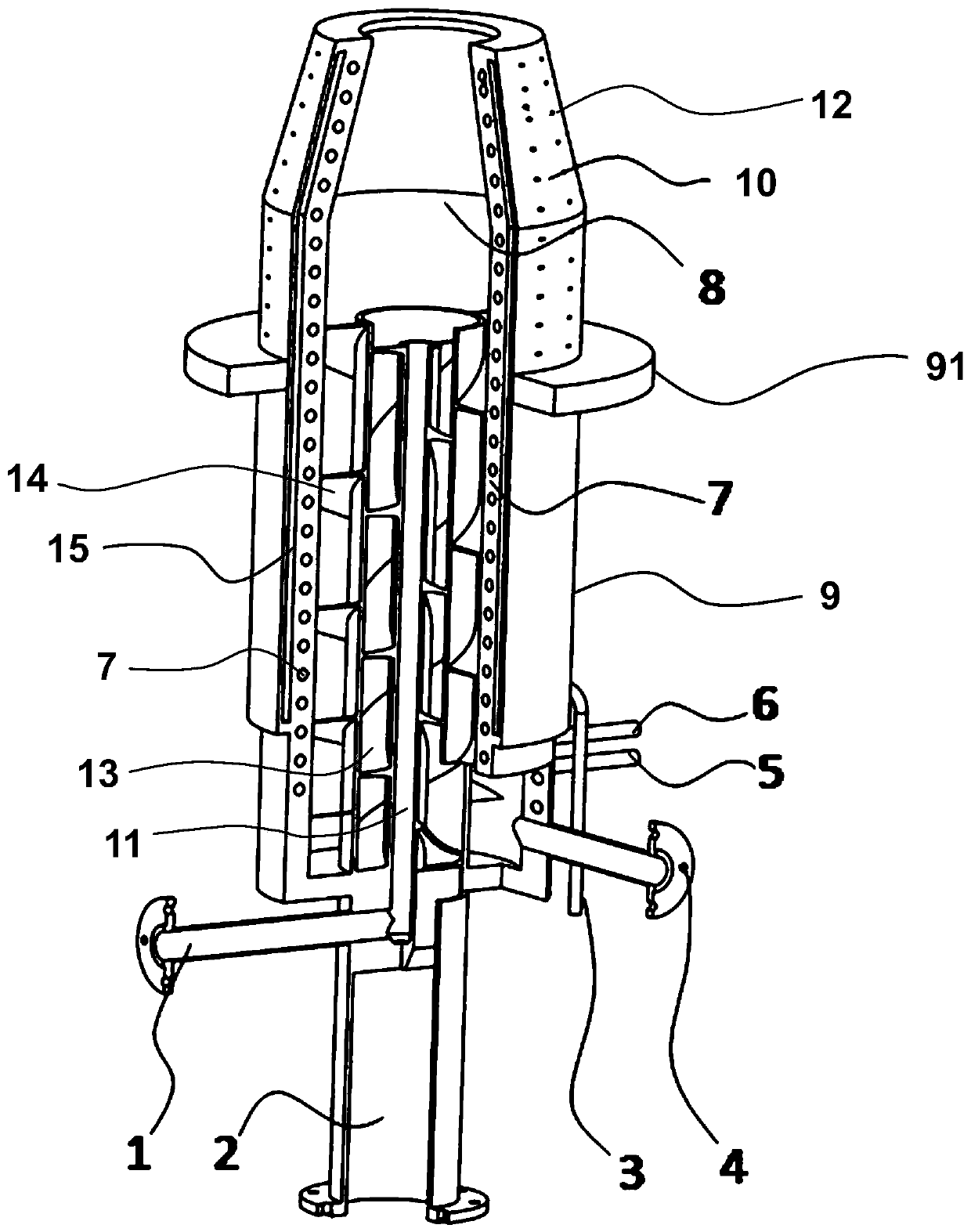
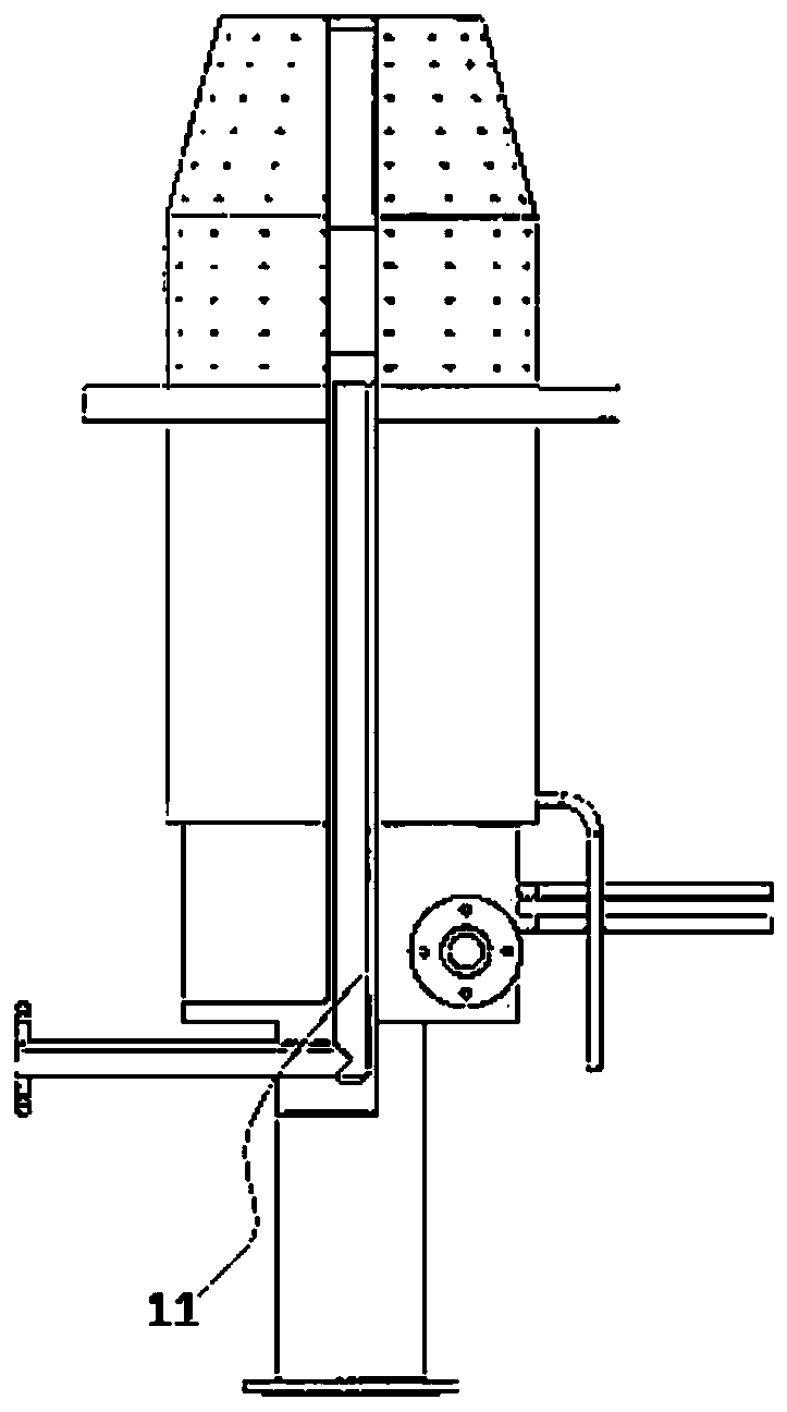
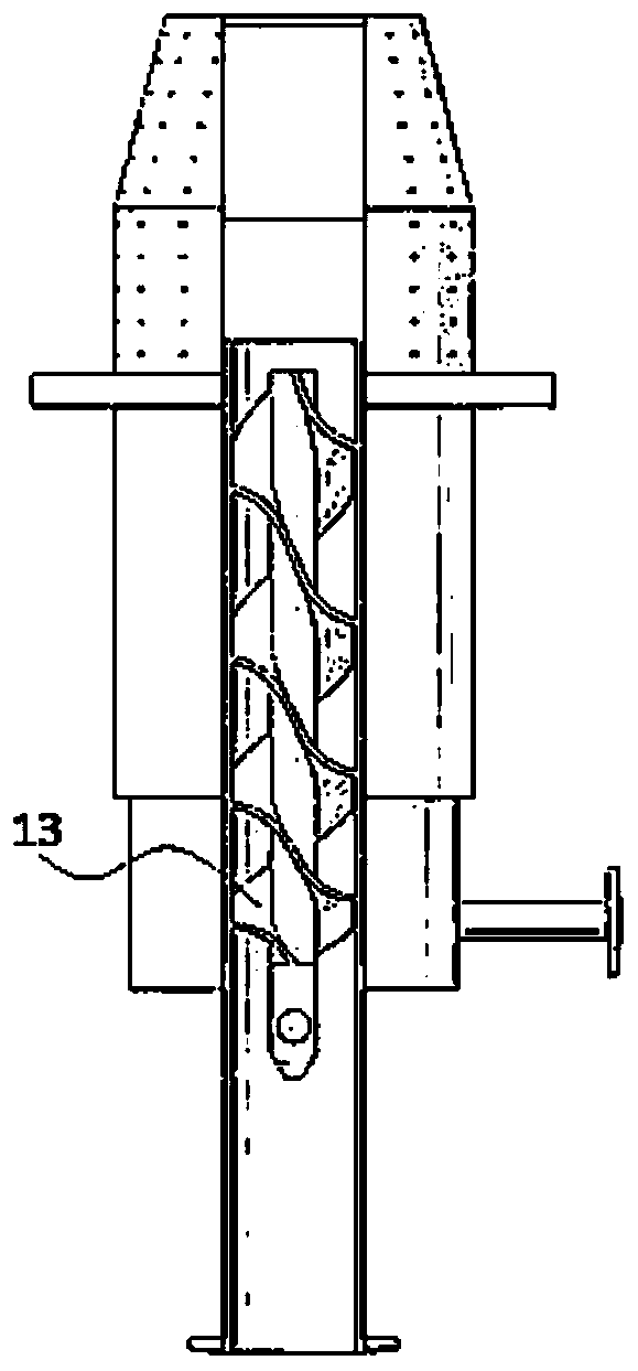
[0021] like Figure 1-5 As shown, a gasifier burner structure with a spiral flow channel includes a burner shell 9, a liquid inlet pipe 2, a vent pipe 11, a first air inlet pipe 4, a second air inlet pipe 1, a compressed air pipe 3, and a water inlet pipe 5 and the water outlet pipe 6; the upper end of the burner shell 9 is formed with a conical mouth portion 10, and the outer side of the upper end of the burner shell 9 is formed with a support ring 91, and the support ring 91 is arranged below the conical mouth portion 10, and the burner shell 9 The lower end of the liquid inlet pipe 2 is closed and interspersed with a vertically distributed liquid inlet pipe 2. The upper end of the liquid inlet pipe 2 is located below the conical mouth portion 10; the outer side of the liquid inlet pipe 2 is formed with at least one first spiral plate 14 outward, and the second The outer sides of a spiral plate 14 are all fixed on the inner wall of the burner shell 9, and one end of the firs...


PUM


Abstract

The invention relates to a gasifier burner structure with a spiral flow channel. The gasifier burner structure comprises a burner casing, a liquid inlet pipe, a vent pipe, a first air intake pipe, a second air intake pipe, a compressed air pipe, a water inlet pipe and a water outlet pipe. According to the structure, through a first spiral plate and a second spiral plate, not only is the rigidity of a burner improved, but the coaxiality of the burner is also ensured, so that the processing error, assembly error and thermal deformation of the flow channel are all limited; meanwhile, the vibration is effectively dispersed, and the probability of mechanical failure is reduced; the first spiral plate and the second spiral plate also accelerate the flow rate of oxygen and fluid respectively and convert the direction of the oxygen and the fluid into a spiral direction; the mixing time in a mixing chamber is longer; the mixing is more sufficient; the atomization effect of coal water slurry is better, and the burning is faster after the coal water slurry is sprayed out of the burner.

Description

technical field [0001] The invention relates to a burner structure of a gasification furnace with a spiral flow channel. Background technique [0002] In the coal-water slurry gasification process, the function of the gasifier burner is to spray the coal-water slurry as fuel into the gasifier for combustion; the coal-water slurry is composed of about 65% coal, 34% water A low-pollution, high-efficiency, pipeline-transportable oil-substituting coal-based fluid fuel obtained through physical processing with 1% additives. [0003] In the existing burner, three layers of pipes with gradually increasing diameters are sheathed together. When burning, the inner pipe and the outer pipe are fed with high-pressure oxygen, and the middle pipe is fed with coal-water slurry. At the end close to the burner outlet, the coal-water slurry is mixed with high-pressure gas, and finally sprayed out through the burner outlet. At the moment of spraying, the volume of the gas expands rapidly, and ...

Claims


Application Information

Patent Timeline
Patent Type & Authority Applications(China)
IPC IPC(8): C10J3/50
CPCC10J3/50C10J2200/152
Inventor 左宸羽陈赤华雍志培
Owner NANJING ZHUANLU TECH
Why Eureka
Try Eureka