Reinforced concrete frame joint beam hogging moment assembled steel structure and reinforcing method thereof

A technology of reinforced concrete and frame beams, applied in building construction, building maintenance, construction, etc., can solve the problems of insufficient reliability, poor fire resistance of chemical materials, easy aging, etc., and improve the negative bending moment bearing capacity of nodes , Improve the efficiency of reinforcement construction, and the effect of less building space occupation

Active Publication Date: 2019-09-27
CHANGAN UNIV
View PDF4 Cites 4 Cited by
  • Summary
  • Abstract
  • Description
  • Claims
  • Application Information

AI Technical Summary

Problems solved by technology

[0002] Due to the change of the building's use function, the load on the reinforced concrete frame beam will change accordingly, which may exceed the original design value, so that the safety of the frame beam does not meet the requirements of the code, especially in the negative moment area, which needs to be reinforced
Existing reinforcement methods include sticking carbon fiber (CRFP) or sticking steel plates, which use chemical glue to stick fiber layers or steel plates on the concrete surface. On the one hand, there are high requirements for the strength level and surface quality of concrete. Poor fire resistance, ea

Method used


Image

  • Reinforced concrete frame joint beam hogging moment assembled steel structure and reinforcing method thereof
  • Reinforced concrete frame joint beam hogging moment assembled steel structure and reinforcing method thereof

Examples


Example Embodiment

[0038] The present invention will be further described in detail below in conjunction with specific embodiments, which are for explanation rather than limitation of the present invention.

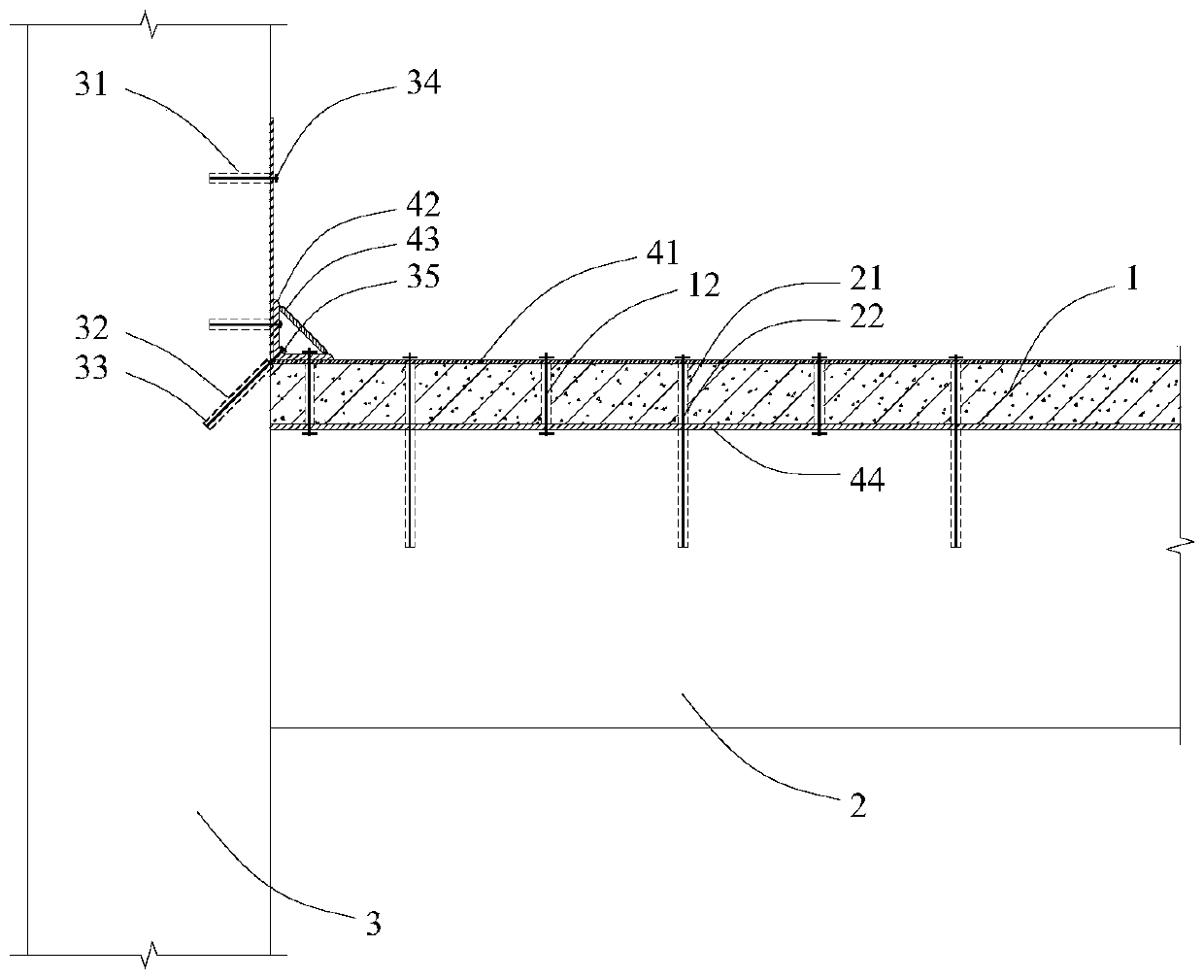
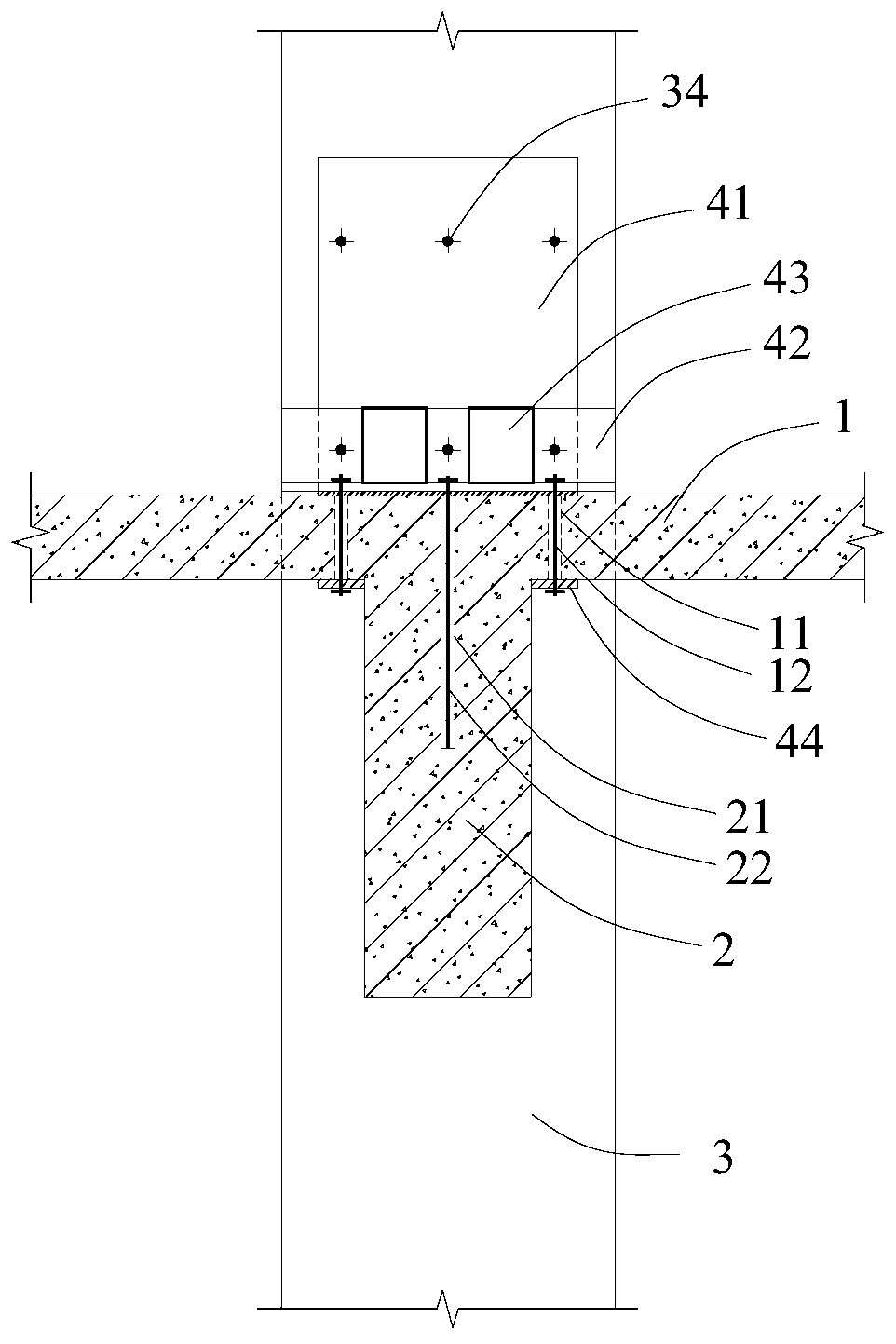
[0039] The present invention is a reinforced concrete frame node beam negative bending moment assembly steel structure, such as figure 1 with figure 2 As shown, it includes a high-strength steel strip 41, an angle steel 42 and a longitudinal steel strip 44 at the bottom of the floor; the reinforced concrete frame node includes a vertical frame column 3, a vertical frame column 3 and a horizontal frame beam 2, and a vertical frame respectively. The column 3 and the frame beam 2 are horizontally arranged on the floor 1 on the frame beam 2; the high-strength steel strip 41 is bent and arranged at right angles to the upper layer of the floor 1 and the frame column 3, and the high-strength steel strip 41 is connected to the frame column 3 by screws. The floor 1 and the frame column 3 are fixed; th...


PUM


Abstract

The invention discloses a reinforced concrete frame joint beam hogging moment assembled steel structure and a reinforcing method thereof. The assembled steel structure comprises a high-strength steel plate belt, angle iron and floor bottom longitudinal steel belts; a reinforced concrete frame joint comprises a frame column which is vertically arranged, a frame beam which is horizontally arranged in a manner of being perpendicular to the frame column and a floor which is perpendicular to the frame column and horizontal to the frame beam and is horizontally arranged on the frame beam; the high-strength steel plate belt is bent to be in right-angle attaching to the upper layer of the floor and the frame column, the high-strength steel plate belt is fixed to the floor and the frame column through screws, the angle iron is fixed to the internal corner of the high-strength steel plate belt, an angle iron vertical limb is fixed to the high-strength steel plate belt and the frame column through screws, the floor bottom longitudinal steel belts are symmetrically arranged on the two sides of the frame beam, and are fixedly attached to the lower layer of the floor in a manner of being close to the frame beam, the horizontal segment of the high-strength steel plate belt is fixed to the floor and the floor bottom longitudinal steel belts through bolts, and the internal corner is fixed to the angle iron horizontal limb, the floor and the floor bottom longitudinal steel belts through bolts.

Description

technical field [0001] The invention relates to the field of reinforcement and assembly structures of civil and construction engineering, in particular to a negative moment assembly steel structure of reinforced concrete frame node beams and a reinforcement method thereof. Background technique [0002] Due to the change of the building's use function, the load on the reinforced concrete frame beam will change accordingly, which may exceed the original design value, so that the safety of the frame beam does not meet the requirements of the code, especially in the negative moment area, which needs to be reinforced. Existing reinforcement methods include sticking carbon fiber (CRFP) or sticking steel plates, which use chemical glue to stick fiber layers or steel plates on the concrete surface. On the one hand, there are high requirements for the strength level and surface quality of concrete. Poor fire resistance and easy aging. Although the tensile strength of carbon fiber or...

Claims


Application Information

Patent Timeline
IPC IPC(8): E04G23/02
CPCE04G23/0218
Inventor 段留省
Owner CHANGAN UNIV
Why Eureka
Try Eureka