A constant elastic coating involute spiral groove long-life sealing device

A technology of sealing device and spiral groove, which is applied in the direction of engine sealing, gas turbine device, jet propulsion device, etc., can solve the problems of end face wear, unreasonable spiral groove shape, and affecting sealing performance, etc., and achieve the best hydrodynamic pressure effect, Avoid the original equilibrium state and enhance the effect of corrosion resistance

Active Publication Date: 2021-01-19
BEIJING CHANGCHENG INST OF METROLOGY & MEASUREMENT AVIATION IND CORP OF CHINA
View PDF10 Cites 0 Cited by
  • Summary
  • Abstract
  • Description
  • Claims
  • Application Information

AI Technical Summary

Problems solved by technology

However, at present, the spiral groove sealing device in the industry still has problems such as serious end face wear and high leakage rate, and seal failure accidents occur from time to time. The main reasons for the above problems in the spiral groove sealing device are as follows:
[0004] 1) The groove shape of the spiral groove is unreasonable
The unreasonable groove shape of the spiral groove leads to poor dynamic pressure effect on the sealing surface, which affects the sealing performance
[0005] 2) There is still wear on the sealing surface
During the working process, due to bearing clearance, vibration and other reasons, the working height of the wave spring changes, resulting in a change in the force value of the wave spring, which destroys the original balance state of the spiral groove sealing device and affects the sealing performance.

Method used


Image

  • A constant elastic coating involute spiral groove long-life sealing device
  • A constant elastic coating involute spiral groove long-life sealing device
  • A constant elastic coating involute spiral groove long-life sealing device

Examples


Embodiment 1

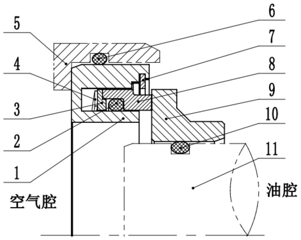
[0026] like figure 1 As shown, a constant elastic coating involute spiral groove long-life sealing device disclosed in this embodiment includes a sealing shell 1, a first sealing rubber ring 2, a pressure plate 3, a lap wave spring 4, and a second sealing rubber ring 6. Back-up ring 7, graphite ring 8, sealing dynamic ring 9 and third sealing rubber ring 10. The constant elastic coating involute spiral groove long-life sealing device is used to isolate the oil cavity from the air cavity, prevent the lubricating oil in the oil cavity from leaking into the air cavity, and achieve the purpose of sealing oil. The lap wave spring 4 is used to generate an axial force, which is transmitted to the graphite ring 8 through the pressing plate 3 to ensure that the graphite ring 8 is in close contact with the sealing dynamic ring 9 to form the main sealing surface; the sealing shell 1 and the machine The box housing 5 is sealed by the second sealing rubber ring 6, the graphite ring 8 and ...


PUM


Abstract

The invention discloses a constant-elasticity film-coating involute spiral groove long-life sealing device, particularly relates to a shaft end sealing device suitable for an aero-engine with high rotating speed, high maneuverability and the complex load, and belongs to the technical field of mechanical sealing. The constant-elasticity film-coating involute spiral groove long-life sealing device comprises a sealing shell, a first sealing rubber ring, a pressing plate, a lap joint wavy spring, a second sealing rubber ring, a check ring, a graphite ring, a sealing movable ring and a third sealing rubber ring. The constant-elasticity film-coating involute spiral groove long-life sealing device is used for isolating an oil cavity from an air cavity and preventing lubricating oil in the oil cavity from leaking to the air cavity so as to fulfill the oil sealing aim. The lap joint wavy spring is used for generating an axial force, the axial force is transmitted to the graphite ring through the pressing plate, tight contact of the graphite ring and the sealing movable ring is guaranteed and a main sealing surface is formed. The constant-elasticity film-coating involute spiral groove long-life sealing device can reduce abrasion of a mechanical sealing device and can improve the sealing property and the stability of the mechanical sealing device, so that the life of the constant-elasticity film-coating involute spiral groove long-life sealing device is prolonged.

Description

technical field [0001] The invention relates to a constant elastic coating involute spiral groove long-life sealing device, in particular to a shaft end sealing device suitable for high-speed, high-mobility, and complex-load aeroengines, and belongs to the technical field of mechanical seals. Background technique [0002] In recent years, with the rapid development of the aviation industry, the requirements for the performance index and efficiency of the aero-engine are getting higher and higher, which leads to the increase of the system temperature, pressure and speed, thus requiring the sealing products to have long life, low leakage, low power consumption and high reliability Features. Ordinary mechanical seals have a large friction factor, high power consumption, severe wear, short life, serious oil leakage, and high use and maintenance costs under high working conditions. [0003] In order to improve the serious wear and tear problem of the traditional mechanical seal ...

Claims


Application Information

Patent Timeline
Patent Type & Authority Patents(China)
IPC IPC(8): F16J15/40F02C7/28
CPCF02C7/28F16J15/164F16J15/40
Inventor 张家远吕成龙吴瑕安敏张昕苏鑫
Owner BEIJING CHANGCHENG INST OF METROLOGY & MEASUREMENT AVIATION IND CORP OF CHINA
Why Eureka
Try Eureka