Indoor water cyclic heating heater

A heater and water circulation technology, applied in heating methods, lighting and heating equipment, household heating, etc., can solve the problems of high power consumption, easy to dry skin, etc., and achieve improved efficiency, increased speed, and comfortable surrounding environment Effect

Inactive Publication Date: 2019-09-27
中山市利德堡电器有限公司
View PDF8 Cites 2 Cited by
  • Summary
  • Abstract
  • Description
  • Claims
  • Application Information

AI Technical Summary

Problems solved by technology

[0004] The purpose of the present invention is to provide an indoor water circulation heating heater to solve the problem in the above-mentioned background technology that the current electric heating wire heater consumes a lot of power and is easy to make the air dry, which makes the skin of the human body easy to dry.

Method used


Image

  • Indoor water cyclic heating heater
  • Indoor water cyclic heating heater
  • Indoor water cyclic heating heater

Examples


Embodiment 1

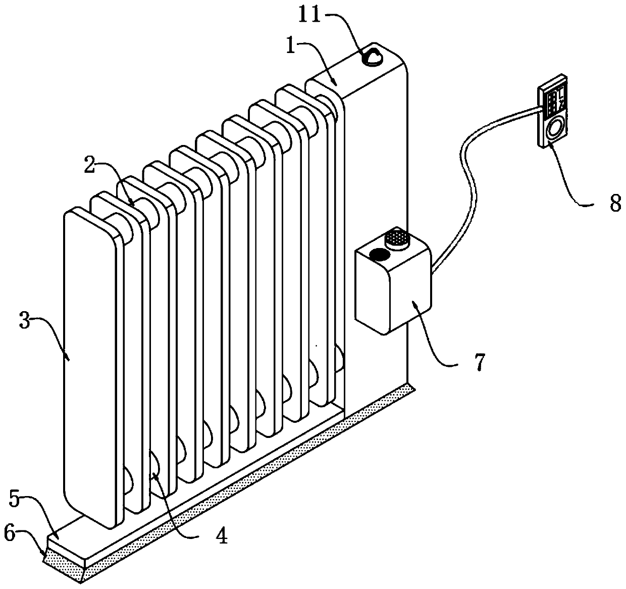
[0031] An indoor water circulation heating heater, such as figure 1 As shown, it includes a heating water tank 1 for containing liquid, a hot water delivery pipe 2 is arranged on the top of one side of the heating water tank 1, and a return pipe 4 is arranged on the bottom of one side of the heating water tank 1, and the hot water delivery pipe 2 and the return pipe 4 are parallel Set, the hot water delivery pipe 2 and the return pipe 4 are connected with several hollow heat dissipation plates 3 that are evenly spaced and arranged in parallel in a linear manner. The hollow heat dissipation plates 3 are used to dissipate the heat in the water into the air and increase the temperature of the surrounding air. , each hollow cooling plate 3 is arranged vertically with the hot water delivery pipe 2 and the return pipe 4 and communicates internally.

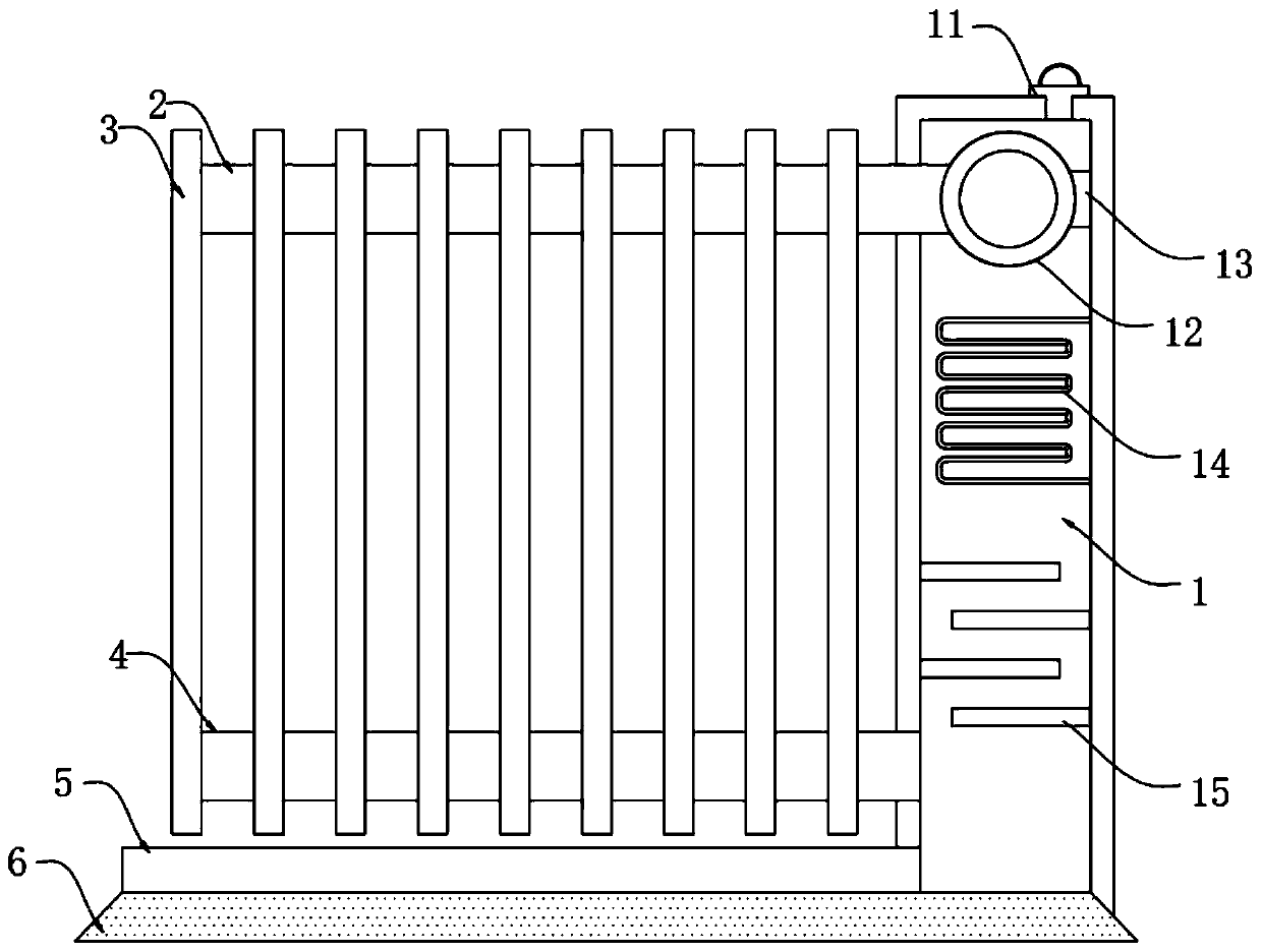
[0032] Further, such as figure 2 As shown, the inside of the heating water tank 1 is equipped with a water pump 12 for pressurized d...

Embodiment 2

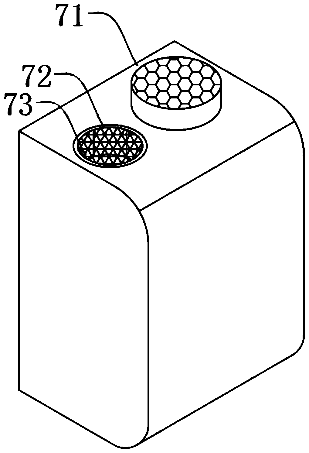
[0040] As a second embodiment of the present invention, such as image 3As shown, the outer wall of the heating water tank 1 is equipped with a humidifying device 7 for increasing the humidity of the surrounding air. The humidifying device 7 includes an ultrasonic atomizer 71. The ultrasonic atomizer 71 is provided with a water inlet 72, and the water inlet 72 is provided with a Filter housing 73 for filtering water.

[0041] Further, such as Figure 4 and Figure 5 As shown, the ultrasonic nebulizer 71 is connected with the temperature and humidity display device 8 through the data line, the temperature and humidity display device 8 is provided with a temperature and humidity sensor 81 and a liquid crystal display 82, and the internal circuit board 84 of the temperature and humidity display device 8 is installed with MCU 85.

[0042] It is worth noting that the ultrasonic nebulizer 71 in this embodiment adopts the NRWT-4 flange type ultrasonic nebulizer, the temperature an...


PUM


Abstract

The invention relates to the technical field of heating equipment, in particular to an indoor water cyclic heating heater. The indoor water cyclic heating heater comprises a heating water tank. A hot water conveying pipe is arranged on the top of one side of the heating water tank, a backflow pipe is arranged at the bottom of one side of the heating water tank, multiple hollow heat dissipation plates uniformly arranged at equal intervals and linearly arranged in parallel are connected to the hot water conveying pipe and the backflow pipe, a humidifying device for increasing the humidity of surrounding air is mounted on the outer wall of the heating water tank, and an ultrasonic atomizer is connected with a temperature and humidity display device through a data line. By means of the heating water tank, the hot water conveying pipe and the hollow heat dissipation plates, water resources are recycled, and environmental protection is achieved; by means of the multiple ultrathin copper-made hollow heat dissipation plates, the temperature dissipation speed is increased; by means of multiple baffles uniformly arranged at equal intervals and arranged in an intersecting manner, water flowing back is prevented from being immediately mixed with heated water; and by means of the ultrasonic atomizer, the temperature and humidity sensor and a single-chip microcomputer, the indoor humidity value can be intelligently controlled, and the surrounding environment is more comfortable.

Description

technical field [0001] The invention relates to the technical field of heating equipment, in particular to an indoor water circulation heating heater. Background technique [0002] People's heating operations are usually achieved by burning relatively cheap coal. With the large-scale heating work, the demand for coal is gradually increasing, and the renewable capacity of coal is relatively slow, which is not conducive to the sustainable use of resources. With the improvement of people's living standards, the requirements for the environment have gradually increased, and the awareness of environmental protection has gradually increased. However, coal-fired heating is not conducive to the sustainable development of the environment. Therefore, this heating technology is contrary to the development of the times. At the same time, coal-fired heating requires a large installation of devices, and coal-fired indoor heating can easily cause the diffusion of pollutants indoors, posin...

Claims


Application Information

Patent Timeline
Patent Type & Authority Applications(China)
IPC IPC(8): F24D19/00F28F21/08F24F6/12F24F11/89F24F11/52
CPCF24D19/00F28F21/085F24F6/12F24F11/89F24F11/52
Inventor 黄文干
Owner 中山市利德堡电器有限公司
Why Eureka
Try Eureka