Electrically-regulated optical chiral structure

A technology of chiral structure and electrical control, applied in the field of optical microstructure, can solve the problems of poor control precision and high cost, and achieve the effect of not easy to fall off, mechanically stable, and high-sensitivity control

Inactive Publication Date: 2019-09-27
中山科立特光电科技有限公司
View PDF0 Cites 7 Cited by
  • Summary
  • Abstract
  • Description
  • Claims
  • Application Information

AI Technical Summary

Problems solved by technology

[0003] Existing optical chiral microstructures mainly achieve circular dichroism control by adjusting the distance between micro-nano structures in the horizontal direction, and the control accuracy is poor; the control of circular dichroism also requires re-preparation of chiral structures, which is costly

Method used


Image

  • Electrically-regulated optical chiral structure
  • Electrically-regulated optical chiral structure
  • Electrically-regulated optical chiral structure

Examples


Embodiment 1

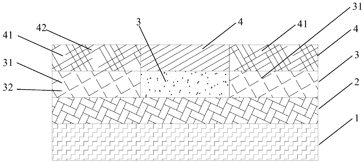
[0026] Such as figure 1 As shown, this embodiment discloses an electrically regulated optical chiral structure, which includes from bottom to top: substrate layer 1, conductive layer 2, electrostrictive layer 3, metal layer 4, substrate layer 1, conductive layer 2, The electrostrictive layer 3 and the metal layer 4 are connected to each other, the electrostrictive layer 3 is provided with not less than one first hole 31, the metal layer 4 is provided with not less than one second hole 41, and the first hole 31 A fixing block 32 is provided, and a metal block 42 is provided in the second hole 41 .

[0027] in particular:

[0028] The metal layer 4, the second hole 41 and the metal block 42 together form a chiral metal micro-nano structure. The first hole 31 is opposite to the second hole 41. The first hole 31 is arranged in a periodic array, and the second hole 41 is in a periodic array. Arranged in a periodic array, the periodic array is rectangular or square. The first hol...

Embodiment 2

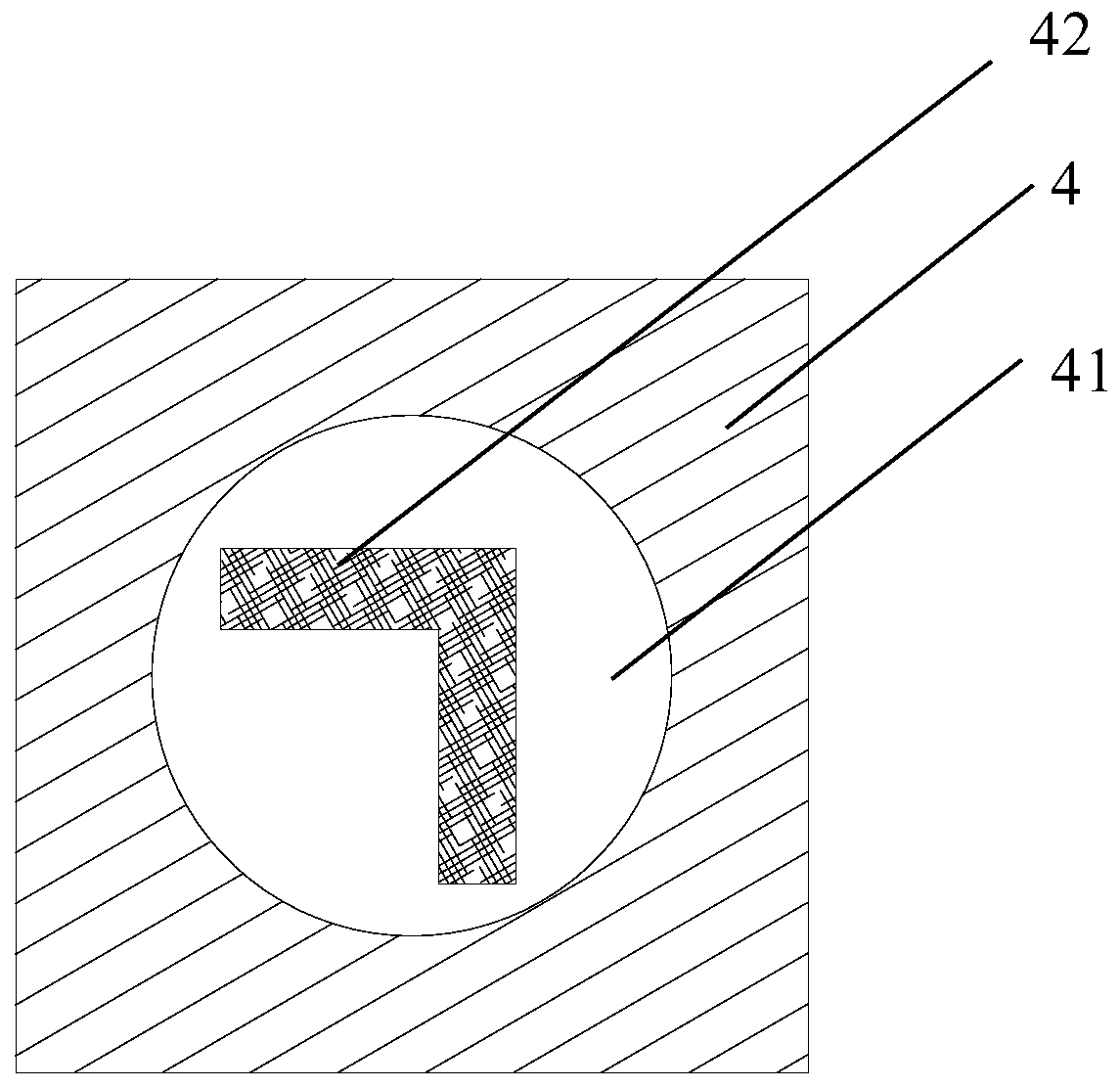
[0035] On the basis of Example 1, such as figure 2 As shown, the second hole 41 is a circular metal hole array, and the metal block 42 is an L-shaped metal block 42 structure. The structure of the L-shaped metal block 42 breaks the structural symmetry of the circular hole, so that the overall structure has chirality. Under the excitation of circularly polarized light with different polarization states, the coupling between the L-shaped metal block 42 structure and the edge of the hole is different, that is to say, the surface plasmons on the metal layer 4 and the surface plasmons on the L-shaped metal block 42 structure are different. The meta-couplings are different, resulting in circular dichroism. In addition, the material of the L-shaped metal block 42 structure is specifically silicon material, that is, the L-shaped silicon material block structure. The silicon material has a high refractive index, and a strong electric field gathers between the silicon structure and t...

Embodiment 3

[0038] The center point of the metal block 42 does not coincide with the center point of the second hole 41 . The metal block 42 is made of noble metal material or silicon material.

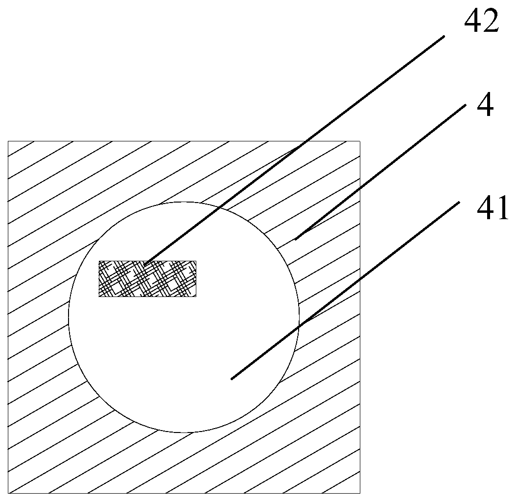
[0039] On the basis of Embodiment 1, the second hole 41 is a square metal hole array, the metal block 42 is a strip-shaped metal block 42 structure, and the center of the strip-shaped metal block 42 structure is not located on the symmetry axis of the square metal hole array. The structure of the strip-shaped metal block 42 is different from the coupling of the edges of the holes in the square metal hole array, which destroys the symmetry of the surface plasmon resonance on the square metal hole array film, thereby generating circular dichroism.

[0040] Such as Figure 4 and Figure 5 It is a circular dichroism curve of a square metal hole array embedded with a strip-shaped metal block 42 structure. The period of the structure is 500nm; the side length of the square metal hole array is 400nm;...


PUM

PropertyMeasurementUnit
lengthaaaaaaaaaa

Abstract

The invention belongs to the technical field of optical microstructure, A chiral structure for electronically regulate and controlling optical property is compose of substrate layer, conductive layer, electrostrictive layer, metal lay, substrate layer, conductive layer, electrostrictive layer and metal layer. That electrostrictive layer is provided with no less than one first hole, the metal layer is provided with no less than one second hole and a fixing block is arranged in the first hole. A metal block is arrange in that second hole, Under the action of applied voltage, the thickness of the electrostrictive layer will also change, and the relative height between the second hole and the metal block will also change, so as to regulate the coupling of the second hole and the isotopic exciton on the middle surface of the metal block, thereby realizing the purpose of electrically regulating the circular dichroism of the optical chiral structure regulating structure of the present invention.

Description

technical field [0001] The invention belongs to the field of optical microstructures, in particular to a structure with optical chirality. Background technique [0002] Optical microstructures can realize beam polarization state control, light field control, surface-enhanced Raman scattering, etc., and have important applications in chiral detection and trace detection. Optical chiral micro-nanostructures can generate circular dichroism and chiral electromagnetic fields, which is an important means to realize polarization state modulation and chirality detection. Optical chiral structures with tunable circular dichroism have important applications in this field. [0003] The existing optical chiral microstructures mainly realize circular dichroism control by adjusting the distance between micro-nano structures in the horizontal direction, and the control accuracy is poor; the control of circular dichroism also requires re-preparation of chiral structures, which is costly. ...

Claims


Application Information

Patent Timeline
Patent Type & Authority Applications(China)
IPC IPC(8): G02B5/00G02B26/00
CPCG02B5/008G02B26/00
Inventor 不公告发明人
Owner 中山科立特光电科技有限公司
Why Eureka
Try Eureka