
Wearable device

A wearable device, the technology of the inner cavity of the shell, which is applied to coupling devices, instruments, clocks and other directions, can solve the problems of difficult assembly, tearing and cracking, and scrapping of the lower shell, so as to reduce the scrap rate of materials, improve the waterproof performance, and the installation structure. simple effect

Inactive Publication Date: 2019-09-27
GOERTEK INC
View PDF5 Cites 3 Cited by
  • Summary
  • Abstract
  • Description
  • Claims
  • Application Information

AI Technical Summary

Problems solved by technology

When connecting with the PCB by soldering, there is little requirement for assembly space, but when the copper pillar needs to be replaced due to poor airtightness, it is necessary to detach the PCB board first to expose the copper pillar for replacement. However, due to the connection between the copper pillar and the PCB Welding conduction, the interference fit between the copper pillar and the watch case, when the PCB board is disassembled, it will inevitably cause tearing and cracking between the copper pillar and the PCB board, resulting in damage to the PCB board, and even the scrapping of the entire lower case; the copper pillar passes through The method of shrapnel and PCB board conduction can effectively solve the above problems. However, this method has a large number of structural parts and requires a large assembly space. It is difficult to assemble in such a small space in the lower case of the watch.

Method used


Image

  • Wearable device
  • Wearable device
  • Wearable device

Examples


Embodiment Construction

[0021] The technical solutions of the present invention will be further described in detail below in conjunction with the accompanying drawings and specific embodiments.

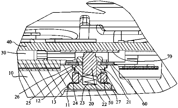
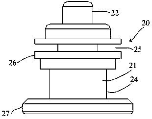
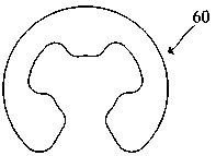
[0022] refer to figure 1 and figure 2 , a wearable device in this embodiment, taking a smart watch as an example, the smart watch includes a watch body and a wristband, the watch body includes a casing and a casing inner cavity, and the casing includes an upper shell and a lower shell, usually the upper shell and the lower shell The fastening encloses the inner chamber of the housing. Since this embodiment is a wearable device, its main improvement is the part of the charging connector on the lower case, then figure 1 Only a schematic diagram of the structure of the installation place of the charging connector of the lower case of the watch case is given in the figure. The lower case 10 is provided with a charging hole 11, and the charging hole 11 is installed with a charging connector 20 extending into t...


PUM


Abstract

The invention provides a wearable device, and the main body of the wearable device comprises a shell and a shell inner cavity, wherein a charging hole is formed in a lower shell, and a charging connector is installed in the charging hole. A PCB is detachably installed in the shell inner cavity. The charging connector comprises a pin head, a pin tube and a spring piece, wherein the pin head abuts against the PCB to achieve conductive connection, and a sealing ring is installed in a first annular groove in the outer surface of the tube wall of the pin tube in a matched mode and is in interference fit with the charging hole. The principle of the charging connector is the same as that of a pogo pin, and the charging connector is conducted with the PCB through stretching and retracting of the pin head. Moreover, the PCB is detachable and convenient to replace, the lower shell and the PCB cannot be damaged, and the rejection rate is reduced; the charging connector is simple in installation structure, convenient to assemble and especially suitable for being installed in a narrow space. The sealing ring is in interference fit with the charging hole, so that the waterproof performance of the charging connector mounting position is greatly improved.

Description

technical field [0001] The present invention relates to structural improvement of wearable devices. Background technique [0002] At present, the charging connectors on wearable devices on the market are mostly solid copper pillars. Taking smart watches as an example, the copper pillars are interference-fitted into the charging hole on the lower case of the watch, and the top end is connected to the PCB by shrapnel or welding. The back of the watch is conductive, and the PCB is fixed to the watch case by thermal fusion. When connecting with the PCB by soldering, there is little requirement for assembly space, but when the copper pillar needs to be replaced due to poor airtightness, it is necessary to detach the PCB board first to expose the copper pillar for replacement. However, due to the connection between the copper pillar and the PCB Welding conduction, the interference fit between the copper pillar and the watch case, when the PCB board is disassembled, it will inevit...

Claims


Application Information

Patent Timeline
IPC IPC(8): H01R13/52H01R13/74H01R13/24H01R12/71G04G17/06
CPCG04G17/06H01R12/712H01R13/2421H01R13/5202H01R13/745
Inventor 张显军杨成黎文军方福平
Owner GOERTEK INC
Learn More