
Beam shielding device for industrial electron accelerator

A technology of electron accelerators and shielding devices, applied in the direction of electrical components, accelerators, etc., can solve the problems of shortened life, hindering equipment maintenance, increasing the cost of air compressors, difficulty in installation, frequency of failure, etc., and achieve the effect of prolonging the service life

Pending Publication Date: 2019-09-27
SHANDONG LANFU HIGH ENERGY PHYSICS TECH CO LTD
View PDF2 Cites 3 Cited by
  • Summary
  • Abstract
  • Description
  • Claims
  • Application Information

AI Technical Summary

Problems solved by technology

[0003] Existing beam blocking devices, such as Patent No. CN201710439026.X "a beam baffle device for swing-type accelerator", use power parts such as solenoid valves and cylinders, and do not shield the power parts; another example is patent CN201220656703.6 "Industrial electron accelerator mobile beam baffle device" uses cylinders to drive connecting rods and rockers to move, and does not shield the cylinders; the first shortcoming of the prior art is that in high radiation and ozone environments, Without effective shielding, the operating stability of cylinders, solenoid valves and other components will be reduced, and the life will be shortened; the second disadvantage is that the cost of the air compressor, the difficulty of installation, and the frequency of failure are increased; the third defect is that the device installation On the side immediately adjacent to the scan box, impeding equipment servicing

Method used


Image

  • Beam shielding device for industrial electron accelerator
  • Beam shielding device for industrial electron accelerator

Examples


Embodiment Construction

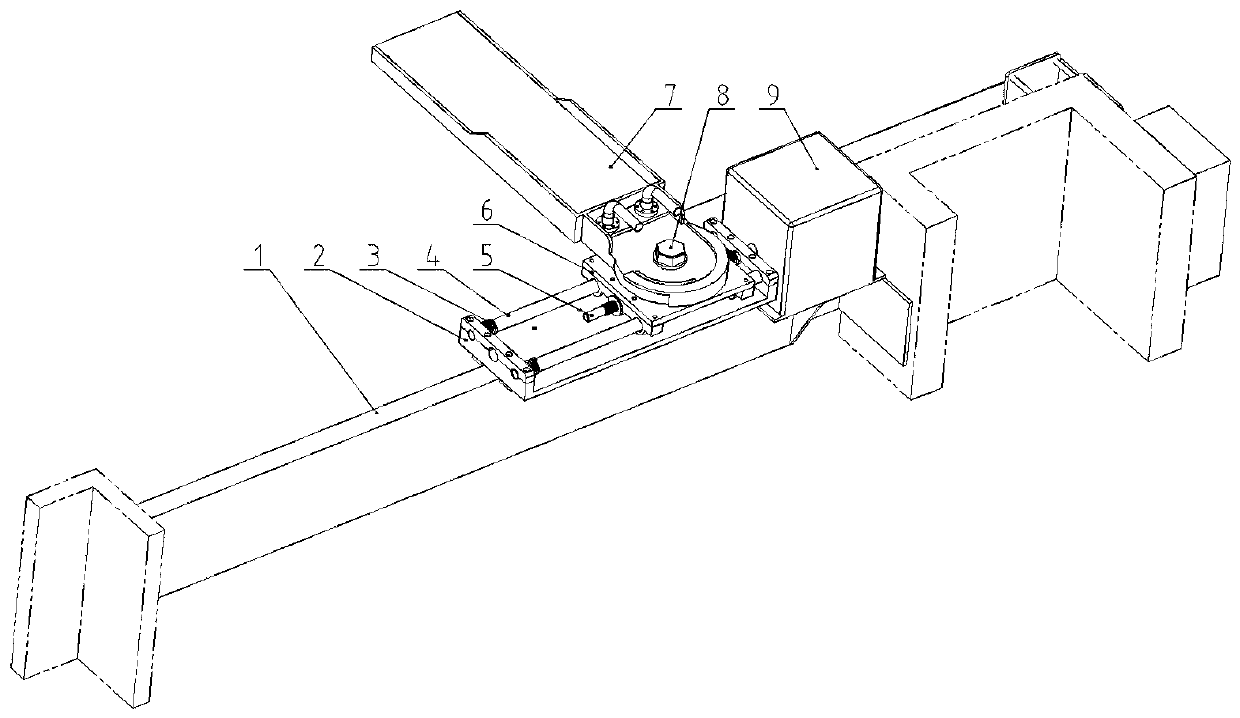
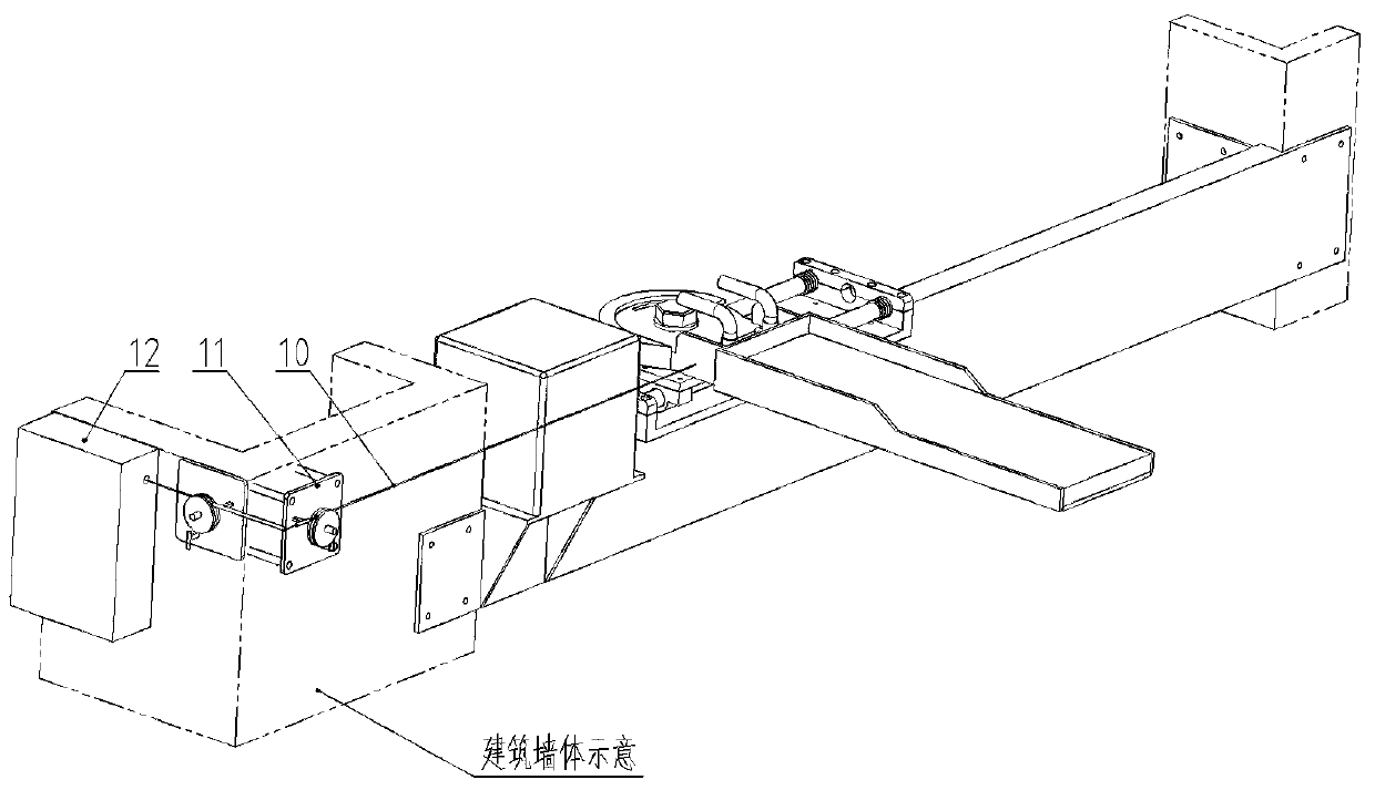
[0017] Installation of the beam shielding device: the main body bracket 1 is installed on the building wall through the fixing plates at both ends, and the upper plane is leveled, and the specific positioning is based on the position of the scanning box; the main part of the stroke base 2 is installed on the main body bracket with bolts 1; Assemble the shift spring 3, stroke guide rod 4, stroke transmission rod 5, and water absorber mounting seat 6, and fasten them to the main body of the stroke base 2 using the pressure plate and bolts of the stroke base 2; the water absorber 7. Fix it on the limit ring of the water absorber mounting seat 6 by fastening the bolt 8; install the motor box 9 on the main body bracket 1 with bolts, and use a coupling to connect the travel transmission rod 5 and the drive shaft of the motor box 9 use bolts to fix the control box 12 to the wall with small electron beam radiation; use the travel cable 10 to connect the water absorber 7 and the travel ...


PUM


Abstract

The invention discloses a beam shielding device for an industrial electron accelerator and relates to the industrial electronic accelerator technology. The beam shielding device for the industrial electron accelerator is characterized by comprising twelve parts such as a main body bracket, a stroke base, a stroke guide rod, a stroke transmission rod, a water absorber mounting seat, a water absorber, a motor box, a stroke cable and a control box, wherein the stroke base is fixed with an upper edge of the main body bracket, the water absorber mounting seat penetrates through the stroke guide rod and the stroke transmission rod through a sliding sleeve and a wire sleeve structure, the stroke transmission rod is driven by a motor through a coupling to rotate to make the water absorber move, the stroke information of the water absorber is transmitted by the stroke cable to a stroke switch, and the water absorber is made to reliably move and position. The beam shielding device is advantaged in that the motor can be shielded, electrical components can be mounted at the position with a small electron beam radiation dose radiation dose, the service life of devices is significantly prolonged, a beam blocking device can be easily turned to the far place, and the sufficient maintenance space is reserved.

Description

technical field [0001] The invention relates to industrial electron accelerator technology, in particular to electron beam current shielding technology. Background technique [0002] The industrial electron accelerator is used to irradiate the goods. It emits an electron beam through the scanning box to scan the moving goods on the conveying line, so that the goods can obtain a predetermined radiation dose. If the conveying line stops due to a sudden failure, or if the goods are jammed due to the shape and displacement of the goods, the goods will be over-irradiated, damaged, heated or even burned, which will pose a great safety risk; moreover, changing the radiation dose of the goods, In the working links such as debugging the beam quality, the electron beam will cause certain damage to the conveyor line without cargo obstruction. Therefore, beam blocking shielding is required in these links. [0003] Existing beam blocking devices, such as Patent No. CN201710439026.X "a ...

Claims


Application Information

Patent Timeline
Patent Type & Authority Applications(China)
IPC IPC(8): H05H7/00
CPCH05H7/00
Inventor 刘华周巩新胜张岩松周国梁陈光荣李传南
Owner SHANDONG LANFU HIGH ENERGY PHYSICS TECH CO LTD
Learn More