
Water lifting and white smoke removal device and water lifting and white smoke removal method thereof

A technology for extracting water and mist from flue gas, which is applied in the direction of combined devices, separation methods, chemical instruments and methods, etc., can solve the problems of high moisture content in flue gas at the outlet, high investment costs, waste of water resources, etc., and achieve low investment , Small footprint and short construction period

Pending Publication Date: 2019-10-01
CHINA JILIANG UNIV
View PDF0 Cites 2 Cited by
  • Summary
  • Abstract
  • Description
  • Claims
  • Application Information

AI Technical Summary

Problems solved by technology

However, in the MGGH process, the moisture contained in the flue gas is discharged to the atmosphere, resulting in a waste of water resources; the outlet flue gas has a large moisture content, requires a large heat exchange area, and high investment costs

Method used


Image

  • Water lifting and white smoke removal device and water lifting and white smoke removal method thereof
  • Water lifting and white smoke removal device and water lifting and white smoke removal method thereof
  • Water lifting and white smoke removal device and water lifting and white smoke removal method thereof

Examples


Embodiment 1

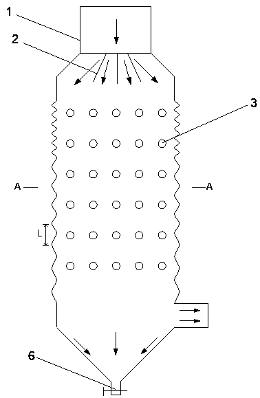
[0041] Such as figure 1 , figure 2 As shown, a water-lifting and whitening device includes a bellows-type casing 4, a flue gas inlet 1 is provided on the top of the bellows-type casing 4, and a plurality of flue gas splitter plates 2 are connected to the lower end of the flue gas inlet 1. The bottom of the bellows type housing 4 is conical, and the bottom end of the conical part is the drain port 6 . The bellows type shell 4 is provided with a smoke outlet 5 close to the upper port of the conical part.

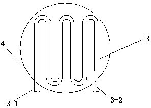
[0042] Several sets of flue gas heat exchange tubes 3 are densely arranged between the flue gas distribution plate 2 and the flue gas outlet 5; each set of flue gas heat exchange tubes 3 is provided with a cooling water inlet 3-1 and a hot water exchange outlet 3-2. The cooling water inlet 3-1 extends from the outside of the bellows type shell 4 to the inside of the bellows type shell 4, and is sealed with the bellows type shell 4; The inside of 4 extends out of the bellow...

Embodiment 2

[0055] As another embodiment, the height of the shell between the lower end of the flue gas distribution pipe 2 and the flue gas outlet 5 is about 26.6 meters, and the internode pitch of the bellows type shell 4 has an equal difference from 2 to 5 cm along the direction of flue gas travel. The sequence increases; the internode spacing is set as follows: 2.00cm, 2.04cm, 2.08cm, 2.16cm...5.00cm from top to bottom.

[0056] According to the formula, the node spacing is calculated according to different flue gas treatments. Generally, the node spacing of the bellows shell is 2-6cm. In special cases, special designs can also be made according to the present invention and formulas.

[0057] Other structures of embodiment 2 are the same as embodiment 1.

[0058] The above high-temperature flue gas can be high-temperature flue gas to be dewatered and whitened in production devices in the fields of metallurgy, chemical industry, steel, thermal power, etc. The specific application of ...


PUM

PropertyMeasurementUnit
Heightaaaaaaaaaa
Diameteraaaaaaaaaa

Abstract

The invention discloses a water lifting and white smoke removal device and a water lifting and white smoke removal method thereof, and belongs to the field of white smoke removal devices. The device comprises a shell, the shell is provided with a smoke inlet and a smoke outlet, and flow dividing plates connected with the smoke inlet are arranged in the shell; the shell is a bellows-type shell; smoke heat-exchange pipes are arranged at the portion, between the lower positions of the flow dividing plates and the smoke outlet, in the shell; a drainage port is formed in the bottom of the shell. According to the water lifting and white smoke removal device, the temperature of high-temperature smoke is reduced through cooling water, so that the water in the smoke is condensed and separated out;meanwhile, when flowing through the bellows-type shell, the smoke regularly shrinks and expands, sound waves with a specific frequency and suitable for droplet agglomeration can be given out to agglomerate droplets, and the agglomerated droplets fall off under the effect of gravity and are drained out of the device through the drainage port. Gas-liquid separation is achieved, energy is sufficiently utilized, water lifting is efficient, besides, the generation of white smoke plume is effectively lowered, and the purpose of removing white smoke is achieved. The device is low in investment and simple in structure, does not cause secondary pollution, and is suitable for application and popularization.

Description

technical field [0001] The invention relates to the field of flue gas whitening devices, in particular to a water lifting whitening device and a water lifting whitening method thereof. Specifically, it relates to an energy-saving device and method for raising water from flue gas and reducing smoke plume in the fields of thermal power, iron and steel, chemical industry, building materials, metallurgy and the like. Background technique [0002] The flue gas temperature of the tail gas emitted by industrial production is relatively high. After a series of pollutant treatment, the tail gas has a high moisture content. When encountering the lower temperature atmosphere at the chimney outlet, it will be cooled rapidly, and the water vapor in the flue gas will condense into Small mist droplets, thus forming white smoke plumes, have caused visual pollution and a certain degree of air pollution, and have received widespread attention. [0003] At present, boiler units in my country ...

Claims


Application Information

Patent Timeline
IPC IPC(8): B01D53/00B01D51/08B01D50/00
CPCB01D53/002B01D51/08B01D50/00B01D2258/0283Y02E20/30
Inventor 张光学吴林陶姚辉辉马振方池作和
Owner CHINA JILIANG UNIV
Learn More