Electric spindle pipeline layout system

An electric spindle and pipeline technology, which is applied in the directions of large fixed members, metal processing machinery parts, maintenance and safety accessories, etc., can solve the problems of complex pipeline layout and design, and achieve high-speed rotation, reduce production costs, and be easy to manufacture. Effect

Pending Publication Date: 2019-10-01
MAANSHAN HENGLIDA MACHINE BLADE +1
View PDF2 Cites 2 Cited by
  • Summary
  • Abstract
  • Description
  • Claims
  • Application Information

AI Technical Summary

Problems solved by technology

[0008] The purpose of the present invention is to overcome the problem of complex pipeline layout design in the electric spindle system in the prior art, and to provide an electric spindle pipeline layout system; The rational layout of axial water inlet channel, axial water outlet channel and axial air inlet channel makes the pipeline structure design of each component in the electric spindle simple and convenient for production and processing. In addition, the pipeline structure design can give full play to lubricating oil, The role of air and cooling water in the electric spindle

Method used


Image

  • Electric spindle pipeline layout system
  • Electric spindle pipeline layout system
  • Electric spindle pipeline layout system

Examples


Embodiment 1

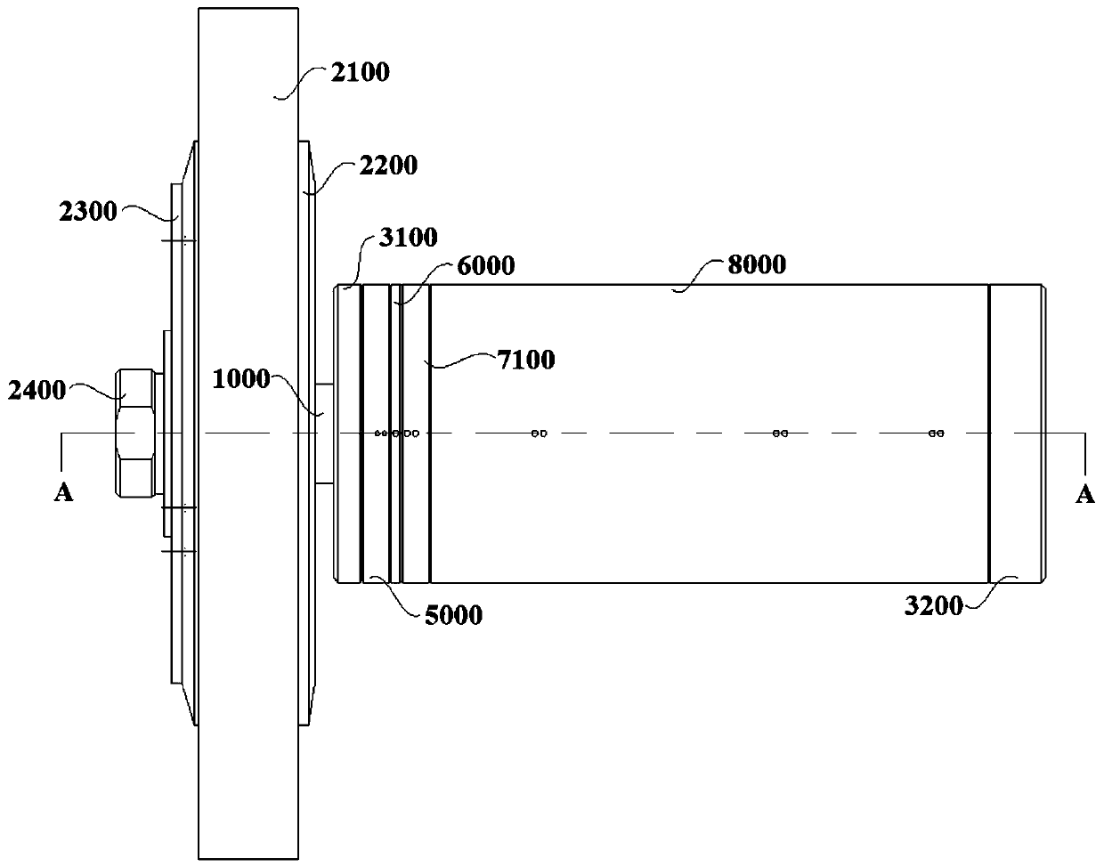
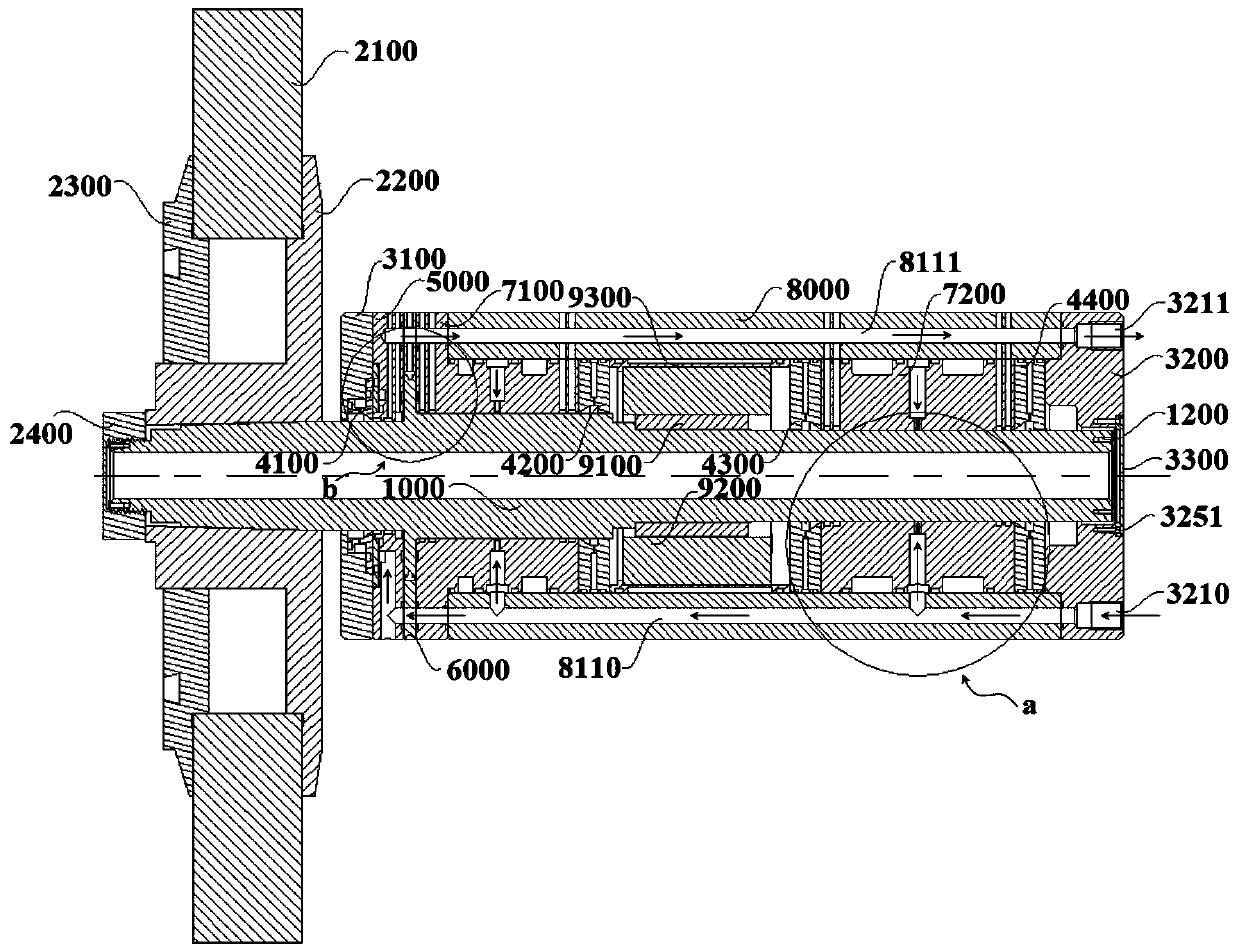
[0070] combine figure 1 , an electric spindle pipeline layout system in this embodiment includes a grinding wheel 2100 installed on the mandrel 1000 and a drive unit, wherein the grinding wheel 2100 is installed on the front end of the mandrel 1000, specifically, combined with figure 1 , figure 2 and Figure 8 , the grinding wheel 2100 is installed on the grinding wheel flange 2200, and the grinding wheel 2100 is fixed on the grinding wheel flange 2200 through the grinding wheel gland 2300; the front end of the mandrel 1000 passes through the grinding wheel flange 2200, and is connected with the The front end of the mandrel 1000 is threaded. The driving unit in this embodiment is arranged in the middle of the mandrel 1000, and is used to drive the mandrel 1000 to rotate, thereby driving the grinding wheel 2100 to rotate, and to grind the workpiece.

[0071] The driving unit in this embodiment includes a rotor 9100 and a stator 9200, such as figure 2 As shown, the rotor 9...

Embodiment 2

[0115] An electric spindle pipeline layout system in this embodiment is basically the same as in Embodiment 1, further: the inclined surface of the trapezoidal inner chamber on the sealing ring in this embodiment and the central axis of the respective corresponding sealing rings The included angle is 15°-75°.

[0116] In this embodiment, the included angle between the inclined surface and the central axis of each corresponding sealing ring may be 15°, 20°, 30°, 45°, 60° or 75°.

[0117] It is worth noting that the inclined surface plays a guiding role in the whole process, and also plays a role of pressurization, guiding the gas flowing into the inner cavity of the sealing ring to the annular groove. The smaller the angle between the axes, the greater the guiding effect of the inclined surface, which is more conducive to guiding the gas into the annular groove; but the smaller the angle between the inclined surface and the central axis of the sealing ring, the greater the dist...

Embodiment 3

[0120] An electric spindle pipeline layout system in this embodiment is basically the same as in Embodiment 2, further: in this embodiment, in order to cool the cooling water in the front annular water channel 7130, the rear annular water channel 7220 or the water cooling channel 9310 The effect is better, the front block 7140 in the front annular water channel 7130 forms a certain angle with the side of the front annular water channel 7130, and the angle is an acute angle, that is, the front block 7140 is arranged obliquely. At the same time, in this embodiment, the positions of the bearing water inlet branch pipes and the bearing water outlet branch pipes located on both sides of the front stopper 7140 are arranged, that is, the position where the bearing water inlet branch pipes communicate with the front annular water channel 7130 is located on one side of the front stopper 7140 Between the acute angle formed by one side of the front annular water channel 7130, the position...


PUM


Abstract

The invention discloses an electric spindle pipeline layout system, and belongs to the technical field of electric spindle design. The electric spindle pipeline layout system comprises a driving unit,a front radial bearing and a rear radial bearing, wherein the driving unit, the front radial bearing and the rear radial bearing are arranged on a mandrel, a shell is wrapped around the outermost endof the mandrel, an axial oil inlet channel, an axial oil outlet channel, an axial water inlet channel, an axial water outlet channel and an axial air inlet channel are axially formed in the shell inthe axial direction of the shell, the axial oil inlet channel and the axial oil outlet channel are symmetric with respect to the central axis of the shell, the axial water inlet channel and the axialwater outlet channel are adjacently arranged, the axial air inlet channel is adjacent to the axial oil inlet channel, an axial air outlet channel and the axial oil outlet channel are the same channel,and oil, gas and water enter corresponding positions through the corresponding channels. According to the electric spindle pipeline layout system, the channels are reasonably arranged, so that the pipeline structure of all the components in the electric spindle is simple in design, production and processing are facilitated, and in addition, due to the structural design of each pipeline, the functions of the oil, the gas and the water in the electric spindle can be fully exerted.

Description

technical field [0001] The invention relates to the technical field of electric spindle design, and more specifically, relates to an electric spindle pipeline layout system. Background technique [0002] Machine tools refer to machines that manufacture machines, and are generally divided into metal cutting machine tools, forging machine tools, and woodworking machine tools. There are many ways to process mechanical parts in modern machinery manufacturing. In addition to cutting, there are casting, forging, welding, stamping, extrusion, etc., but for parts with high precision requirements and finer surface roughness requirements, they generally need to be processed. The final machining is done by cutting on the machine tool. [0003] The machine tools in the prior art are developing towards high precision, high efficiency and high speed. Among them, the electric spindle is used in high-speed ultra-precision machine tools due to its performance advantages such as high rotatio...

Claims


Application Information

Patent Timeline
Patent Type & Authority Applications(China)
IPC IPC(8): B23Q1/70B23Q11/12B23B19/02
CPCB23Q1/70B23Q11/12B23Q11/127
Inventor 高思煜张增明谢敏俞伟锋王伟
Owner MAANSHAN HENGLIDA MACHINE BLADE
Why Eureka
Try Eureka