Optical fiber smoke sensing temperature fire automatic alarm linkage control system

A technology of linkage control system and automatic fire alarm, which is applied to fire alarms that rely on smoke/gas action and fire alarms that rely on electricity, can solve the problems of poor alarm and fire protection effects, etc., to ensure accuracy and eliminate various fire alarms. flaws, ensuring comprehensive effects

Pending Publication Date: 2019-10-01
深圳晶点光科有限公司
View PDF0 Cites 3 Cited by
  • Summary
  • Abstract
  • Description
  • Claims
  • Application Information

AI Technical Summary

Problems solved by technology

[0005] The purpose of the present invention is to overcome the disadvantages and problems existing in the prior art that the fire alarm system is constructed using electronic technology, and the alarm and fire protection effect is poor, and to provide a fiber optic sensor that does not use electronic technology to construct a fire alarm system and has a good alarm and fire protection effect. Smoke-sensing, temperature and fire automatic alarm linkage control system

Method used


Image

  • Optical fiber smoke sensing temperature fire automatic alarm linkage control system
  • Optical fiber smoke sensing temperature fire automatic alarm linkage control system

Examples


Embodiment 1

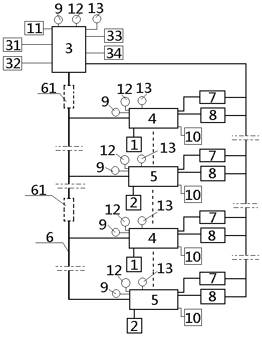
[0045] see figure 1 and figure 2 , an optical fiber smoke and temperature automatic fire alarm linkage control system, comprising a fire linkage controller 3, at least one smoke fire alarm controller 4, at least one temperature fire alarm controller 5, the smoke fire alarm controller 4, The temperature fire alarm controllers 5 are all signally connected to the fire linkage controller 3 through the main optical fiber 6, between two smoke fire alarm controllers 4 or between two temperature fire alarm controllers 5 or smoke fire alarm controllers 4, temperature fire The alarm controllers 5 are connected in parallel; the fire detectors include a fiber-optic smoke detector 1 and a fiber-optic temperature-sensitive fire detector 2, and a single smoke fire alarm controller 4 communicates with multiple fiber-optic smoke detectors through an optical fiber. Fire detector 1 is used for signal connection, a single temperature-sensitive fire detector is connected to multiple fiber-optic ...

Embodiment 2

[0048] Basic content is the same as embodiment 1, the difference is:

[0049] The main optical fiber 6 is provided with a communication repeater 61, and the setting point of the communication repeater 61 is between the fire linkage controller 3 and the smoke fire alarm controller 4 or between the smoke fire alarm controller 4 and the temperature fire alarm controller. 5 or between fire linkage controller 3 and temperature fire alarm controller 5.

Embodiment 3

[0051] Basic content is the same as embodiment 1, the difference is:

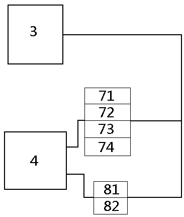
[0052] The linkage control device 7 includes any one or two of the fire door controller 71, the smoke control controller 72, the elevator forced landing controller 73, the adjacent floor power failure controller 74, and the fire broadcasting (no number) Or any three or any four or all. The fire extinguishing controller 8 includes any one or all of a gas fire extinguishing controller 81 and a fire pump controller 82 .


PUM


Abstract

An optical fiber smoke sensing temperature fire automatic alarm linkage control system is provided. The system comprises a fire linkage controller, at least one smoke fire alarm controller, and at least one temperature fire alarm controller. The fire linkage controller is in a signal connection with the smoke fire alarm controller and the temperature fire alarm controller by using the optical fiber; the fire linkage controller, the smoke fire alarm controller, and the temperature fire alarm controller are in a signal connection with a manual fire alarm button, a manual fire hydrant button, a linkage control device, and a fire extinguishing controller by using the optical fiber; and the smoke fire alarm controller and the temperature fire alarm controller are in a signal connection with a corresponding fiber-optic smoke-sensed detector and a corresponding fiber-optic temperature-sensed detector by using the optical fiber. According to the design of the present invention, not only the optical fiber technology can be used to build a fire alarm system with a better fire alarm effect, but also high precision, strong safety and a wide control area can be realized.

Description

technical field [0001] The invention relates to a fire alarm system, in particular to an optical fiber smoke and temperature sensing fire automatic alarm linkage control system, which is particularly suitable for comprehensively constructing a fire alarm system using optical fiber technology to improve the effect of alarm and fire protection. Background technique [0002] With the rapid development of urban construction, the scale of the city continues to expand and the population continues to increase, followed by various types of fires, especially the probability of major fires gradually increasing, and timely and effective fire detection and alarm, fire extinguishing signals, It is one of the most effective means to reduce fire losses. For this reason, it is necessary to establish an automatic fire alarm system. [0003] Although the existing automatic fire alarm system also has the function of detection and alarm, most of the parts it adopts are based on electronic techn...

Claims


Application Information

Patent Timeline
Patent Type & Authority Applications(China)
IPC IPC(8): G08B17/06G08B17/10
CPCG08B17/06G08B17/10
Inventor 张森
Owner 深圳晶点光科有限公司
Why Eureka
Try Eureka