Micro-nano compression device

A compression device and micro-nano technology, applied in the field of biological sciences, can solve the problems of limited compression force, sample temperature rise, movement, etc., and achieve good compression effect

Pending Publication Date: 2019-10-08
JINHUA VOCATIONAL TECH COLLEGE
View PDF0 Cites 1 Cited by
  • Summary
  • Abstract
  • Description
  • Claims
  • Application Information

AI Technical Summary

Problems solved by technology

[0002] In recent years, it has become more and more important to study the response of biological cells to external pressure stimuli at the molecular scale. Generally, the existing technology uses contact probe technology such as micro-press plate, micro-nano indentation technology, atomic force microscope, etc. The biological sample on the substrate exerts a unidirectional force, which has the disadvantage of causing the sample to move in the uncompressed direction, which affects the compression eff

Method used


Image

  • Micro-nano compression device
  • Micro-nano compression device
  • Micro-nano compression device

Examples


Embodiment Construction

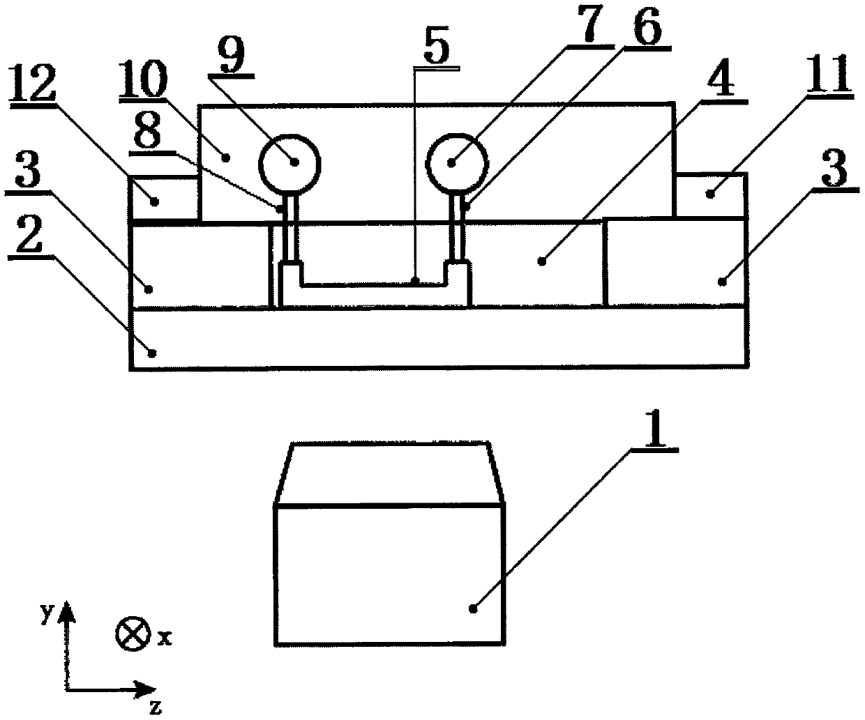
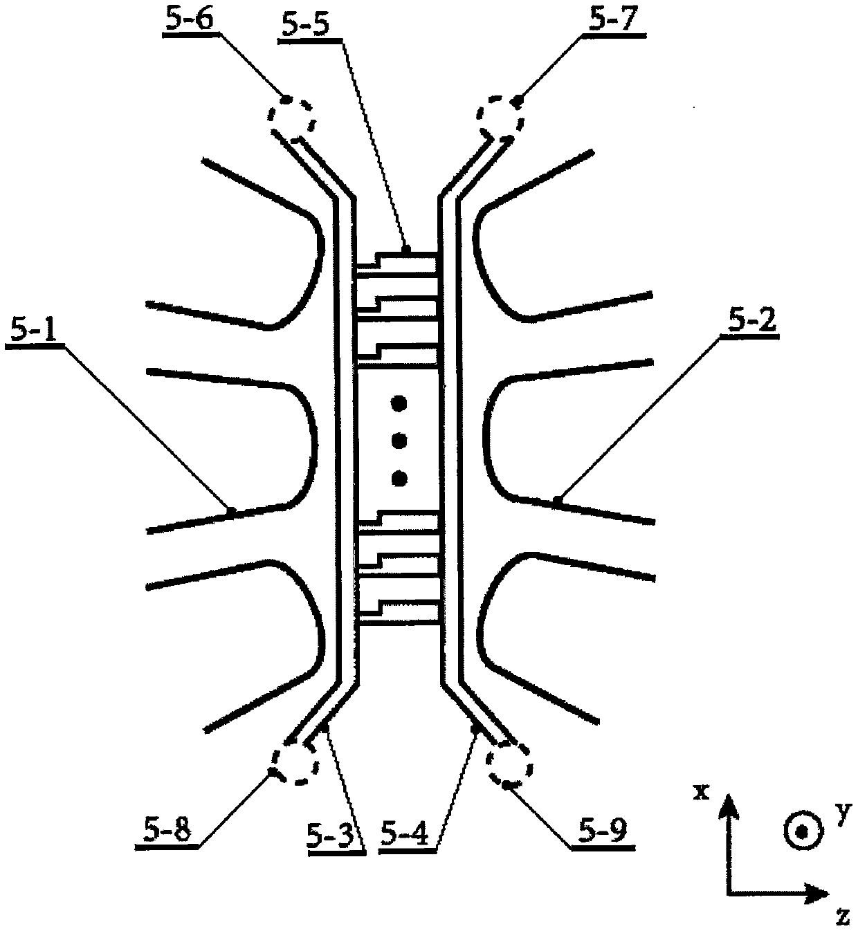
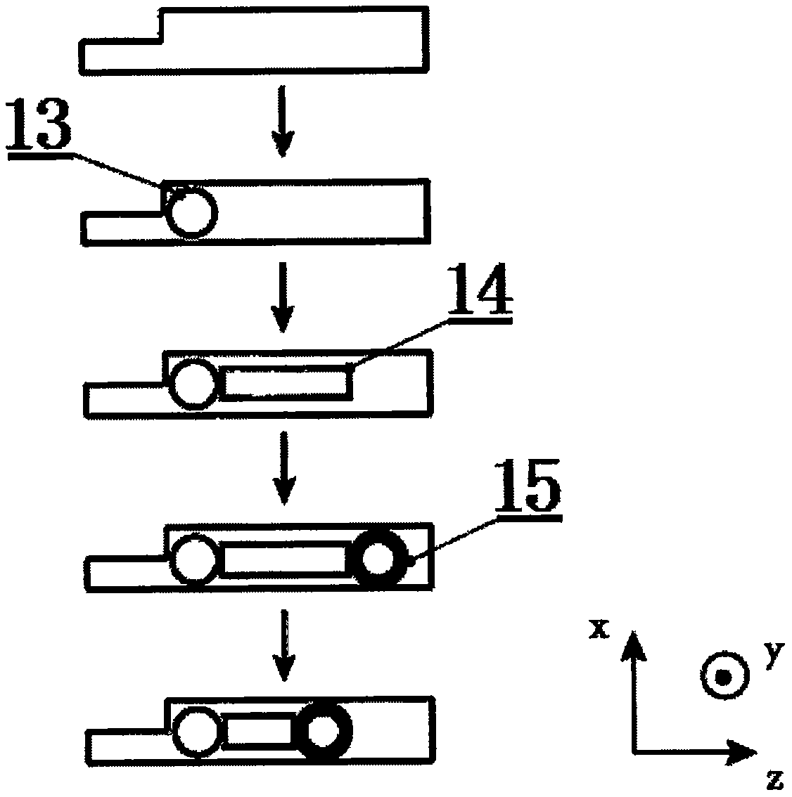
[0022] like figure 1 It is a schematic diagram of the present invention, including optical microscope (1), glass substrate (2), metal foil (3), filling layer (4), micro compressor (5), liquid inlet pipe (6), liquid inlet (7) , liquid outlet pipe (8), liquid outlet (9), protective layer (10), electromagnet I (11), electromagnet II (12), voltage source and cable, xyz is a three-dimensional coordinate system, and the compression experiment material has high Molecular spheres (13), macromolecular samples (14), magnetic spheres (15) and liquid, a microcompressor (5) is connected to the middle position above the glass substrate (2), and deposits with a thickness of The metal foil (3) of 500 microns, the remaining space of 500 microns height above the glass substrate (2) is a filling layer (4), and the filling layer (4) completely covers the microcompressor (5), and the filling layer (4) is Siloxane material; the liquid inlet (7) is connected to the port II (5-7) of the micro compre...


PUM

PropertyMeasurementUnit
Thicknessaaaaaaaaaa
Lengthaaaaaaaaaa
Widthaaaaaaaaaa

Abstract

The invention relates to the technical field of biological science, particularly to a micro-nano compression device comprising an optical microscope, a glass substrate, a metal foil, a filling layer,a micro compressor, a liquid inlet tube, a liquid inlet, a liquid outlet tube, a liquid outlet, a protective layer, an electromagnet I, an electromagnet II, a voltage source and a cable. A small polymer sphere, a macromolecular sample, a small magnetic sphere and liquid are employed as compression experimental materials. The micro compressor includes a metal probe I, a metal probe II, a microchannel I, a microchannel II, a compression channel, a port I, a port II, a port III, and a port IV. The optical microscope is arranged at the position at a distance of 10 cm below the glass substrate. Themicrofluidic structure is combined with the magnetic force to apply a compression force on a biological target in confined space; the sample position is limited relatively during the compression process; and the compression effect is good. Moreover, the pressure application environment is similar to the original living environment of the biological sample; and the existing commercial optical microscope can be used for monitoring the compression process, so that sample deterioration is avoided.

Description

technical field [0001] The invention relates to the technical field of biological sciences, in particular to a micro-nano compression device for applying compression force to a biological target in a limited space and observing its response. Background technique [0002] In recent years, it has become more and more important to study the response of biological cells to external pressure stimuli at the molecular scale. Generally, the existing technology uses contact probe technology such as micro-press plate, micro-nano indentation technology, atomic force microscope, etc. The biological sample on the substrate exerts a unidirectional force, which has the disadvantage of causing the sample to move in the uncompressed direction and affecting the compression effect. Other existing technologies use optical traps to manipulate small balls located in microfluidic channels to The sample exerts a compressive force, which uses a laser to generate the force. However, since the local h...

Claims


Application Information

Patent Timeline
IPC IPC(8): G01N3/08G01N3/06G01N21/84G01N33/483
CPCG01N3/068G01N3/08G01N21/84G01N33/4833G01N2203/0019G01N2203/005G01N2203/0085G01N2203/0286G01N2203/0298G01N2203/0647
Inventor 郭强索奕双张向平
Owner JINHUA VOCATIONAL TECH COLLEGE
Why Eureka
Try Eureka