
An ultra-light satellite portable station

A portable station, ultra-light technology, applied in the field of communication satellites, can solve the problems of no fast angle adjustment + angle fine-tuning structure, heavy equipment weight, communication equipment failure, etc., to shorten the satellite alignment time, ensure strength, and reduce weight.

Active Publication Date: 2020-08-21
NANJING CHINA SPACENET SATELLITE TELECOM
View PDF7 Cites 0 Cited by
  • Summary
  • Abstract
  • Description
  • Claims
  • Application Information

AI Technical Summary

Problems solved by technology

[0003] 1. The electrical box is at the bottom of the antenna, so it does not have the ability to ford;
[0004] 2. The feed bracket part contains power amplifiers, radio frequency and other equipment that are heavy, but there is no corresponding counterweight on the back of the antenna surface, so the center of the pitch rotation part is offset from the front end, and a larger reducer and motor are required for pitch rotation;
[0005] 3. The antenna electrical box is located at the front end of the antenna, and it is easily exposed to direct sunlight when the temperature is high in summer, causing the temperature inside the box to rise abnormally, resulting in failure of communication equipment;
[0006] 4. The antenna surface is assembled with multi-lobe buckles, and there is a certain amount of assembly time when the antenna is erected
[0007] 5. The weight is heavy, which cannot meet the needs of the increasingly miniaturized antenna
[0012] 3. The overall structure of the antenna is heavy, and it can only be carried in a box and cannot be carried on the back. It is inconvenient to carry in complex terrain such as mountainous areas;
[0013] 4. The manual adjustment structure of azimuth and pitch is slow, and there is no fast angle adjustment + angle fine-tuning structure;
[0014] The control box is small in size, it can only place the control part and drive part of the antenna itself, and there is no space for the built-in modem and other business equipment

Method used


Image

  • An ultra-light satellite portable station
  • An ultra-light satellite portable station
  • An ultra-light satellite portable station

Examples


Embodiment Construction

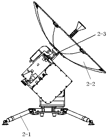
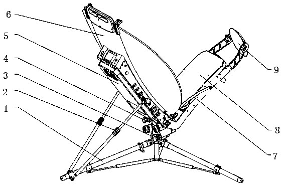
[0050] The present invention is described in further detail now in conjunction with accompanying drawing. These drawings are all simplified schematic diagrams, which only illustrate the basic structure of the present invention in a schematic manner, so they only show the configurations related to the present invention.

[0051] see Figure 3-Figure 10. It should be noted that the structures, proportions, sizes, etc. shown in the drawings attached to this specification are only used to match the content disclosed in the specification, for those who are familiar with this technology to understand and read, and are not used to limit the implementation of the present invention. Limiting conditions, so there is no technical substantive meaning, any modification of structure, change of proportional relationship or adjustment of size, without affecting the effect and purpose of the present invention, should still fall within the scope of the present invention. The disclosed technic...


PUM


Abstract

The present application relates to the technical field of communication satellites, and in particular to an ultralight satellite portable station, which comprises an antenna assembly and a support frame. The antenna assembly comprises an antenna surface, a feed support, a pitch transmission mechanism, and an azimuth transmission mechanism. An electrical box is integrated on the back side of the antenna surface. The feed support is located on both sides of the antenna surface. The feed support is connected to the pitch transmission mechanism. The pitch transmission mechanism is connected to the azimuth transmission mechanism. The azimuth transmission mechanism is connected to the support frame by means of a fast installation mechanism. The front side of the antenna surface is connected at fixed included angles to a radio frequency transceiver assembly and a secondary reflection surface by means of a radio frequency transceiver assembly limit rod. An antenna controller, a satellite modem, a built-in device and so on are placed on the back side of the antenna surface, thereby preventing the direct irradiation of sunlight and optimizing the counterweight of the antenna. The antenna surface employs a folding hinge design, which eliminates the need for traditional multi-lobe assembly links, greatly saves on installation time and enhances the integrity of the antenna.

Description

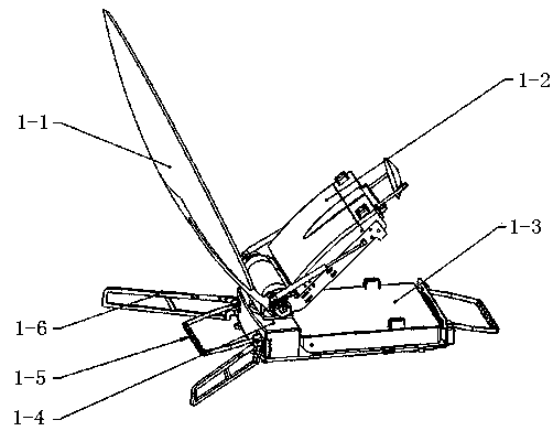
technical field [0001] The invention relates to the technical field of communication satellites, in particular to an ultra-light satellite portable station. Background technique [0002] In existing applications, the bias-fed satellite antenna generally adopts a box structure, such as figure 1 As shown: the whole antenna generally consists of antenna surface 1-1, feed source bracket 1-2, feed source system, azimuth and pitch transmission parts 1-4, electrical box 1-3, windproof bracket 1-6, handle 1-5, etc. Composed of components, the electrical box and the azimuth and pitch transmission parts are installed on the bottom plate of the antenna structure, and the antenna feeder system is installed on the azimuth and pitch transmission parts of the antenna. This kind of antenna structure meets normal communication needs, and has the advantages of compact volume after storage, large volume of electrical box, and multiple communication machines built in. But there are certain di...

Claims


Application Information

Patent Timeline
Patent Type & Authority Patents(China)
IPC IPC(8): H01Q19/19H01Q15/16H01Q3/08H01Q1/12H01Q5/00H04B7/185
CPCH01Q1/1235H01Q3/08H01Q5/00H01Q15/162H01Q19/19H04B7/18517
Inventor 鞠正锋李玮刘涛李文明程新
Owner NANJING CHINA SPACENET SATELLITE TELECOM
Learn More