Scanning light source output gain flatness improving device and scanning light source

An output gain, gain flat technology, applied in the field of optical communication, can solve the problem of poor output gain flatness of scanning light source, and achieve the effect of good gain balance

Inactive Publication Date: 2019-10-08
THE 13TH RES INST OF CHINA ELECTRONICS TECH GRP CORP
View PDF6 Cites 3 Cited by
  • Summary
  • Abstract
  • Description
  • Claims
  • Application Information

AI Technical Summary

Problems solved by technology

[0003] In view of this, an embodiment of the present invention provides a scanning light source output gain flatness improving device and a scanning light source to solve the problem of poor output gain flatness of the scanning light source in the prior art

Method used


Image

  • Scanning light source output gain flatness improving device and scanning light source
  • Scanning light source output gain flatness improving device and scanning light source
  • Scanning light source output gain flatness improving device and scanning light source

Examples


Embodiment Construction

[0023] In the following description, specific details such as specific system structures and technologies are presented for the purpose of illustration rather than limitation, so as to thoroughly understand the embodiments of the present invention. It will be apparent, however, to one skilled in the art that the invention may be practiced in other embodiments without these specific details. In other instances, detailed descriptions of well-known systems, devices, circuits, and methods are omitted so as not to obscure the description of the present invention with unnecessary detail.

[0024] In order to illustrate the technical solutions of the present invention, specific examples are used below to illustrate.

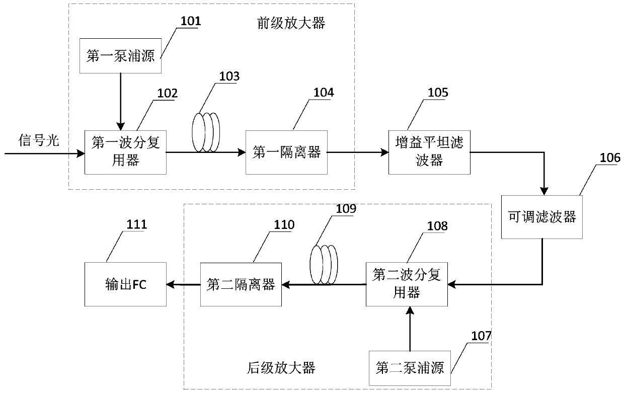
[0025] see figure 1 , an embodiment of the present invention provides a scanning light source output gain flatness improving device, comprising: a first wavelength division multiplexer 102, a first erbium-doped optical fiber 103, a first isolator 104, and a gain flatte...


PUM


Abstract

The invention is applicable to the technical field of optical communication, and provides a scanning light source output gain flatness improving device and a scanning light source. The device comprises a first wavelength division multiplexer, a first Er-doped fiber, a first isolator, a gain flattening filter, an adjustable filter, a second wavelength division multiplexer, a second Er-doped fiber,a second isolator and an output FC which are sequentially connected, and further comprises a first pumping source connected with the first wavelength division multiplexer and a second pumping source connected with the second wavelength division multiplexer; signal light is amplified by a pre-stage amplifier composed of a first pumping source, a first wavelength division multiplexer, a first Er-doped optical fiber, a first isolator and a gain flattening filter and then enters an adjustable filter to be filtered; the filtered signal light passes through a post-stage amplifier composed of a second pumping source, a second wavelength division multiplexer, a second erbium-doped fiber and a second isolator and then scanning light is output through an output FC; the unevenness caused by the pre-stage amplifier, the unevenness caused by the post-stage amplifier and the unevenness caused by high-speed scanning of the scanning light are superposed and complemented, so that good gain equalizationis realized.

Description

technical field [0001] The invention belongs to the technical field of optical communication, and in particular relates to a scanning light source output gain flatness improvement device and a scanning light source. Background technique [0002] The C-band high-power high-speed scanning light source has the characteristics of large tuning range, narrow bandwidth, fast wavelength tuning speed, and stable performance. It plays an important role in both optical fiber communication systems and fiber grating sensing. However, due to the influence of bait ions, the main working substance in the erbium-doped optical fiber, the optical conversion efficiency in the C-band range is different, resulting in poor gain flatness of optical signals of different wavelengths. After the stage, the unevenness of the gain is more obvious, especially in the case of high-speed scanning, the unevenness is more obvious, resulting in a large distortion of the optical signal, which affects its use in ...

Claims


Application Information

Patent Timeline
Patent Type & Authority Applications(China)
IPC IPC(8): H04B10/25G02B6/293
CPCG02B6/293H04B10/25891
Inventor 程义涛王英顺韩玲张厚博沈牧
Owner THE 13TH RES INST OF CHINA ELECTRONICS TECH GRP CORP
Why Eureka
Try Eureka