
Transcatheter implanted aortic valve stent

A technology of aortic valve and aorta, applied in the direction of heart valve, etc., can solve problems such as difficult adjustment of stent, displacement falling off, slipping into the left ventricle, etc., and achieve the effect of improving surgical safety, precise positioning, and reducing accidental displacement

Pending Publication Date: 2019-10-11
陈绍良 +1
View PDF0 Cites 1 Cited by
  • Summary
  • Abstract
  • Description
  • Claims
  • Application Information

AI Technical Summary

Problems solved by technology

The first is that the positioning of the stent is difficult, and the existing stent is difficult to adjust after release, and there is a serious risk of displacement and falling off, thereby slipping into the left ventricle or aorta

Method used


Image

  • Transcatheter implanted aortic valve stent
  • Transcatheter implanted aortic valve stent
  • Transcatheter implanted aortic valve stent

Examples


Embodiment 1

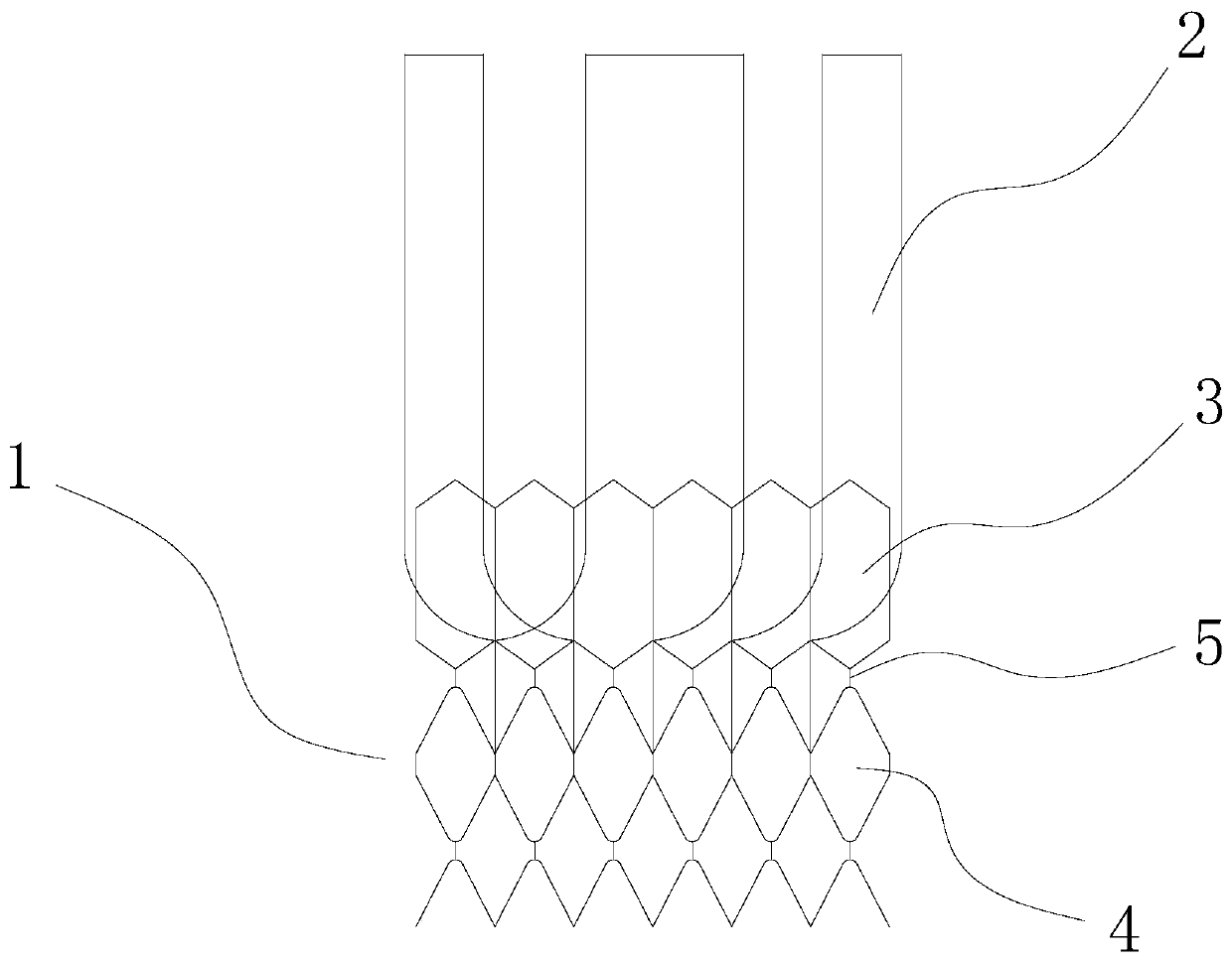
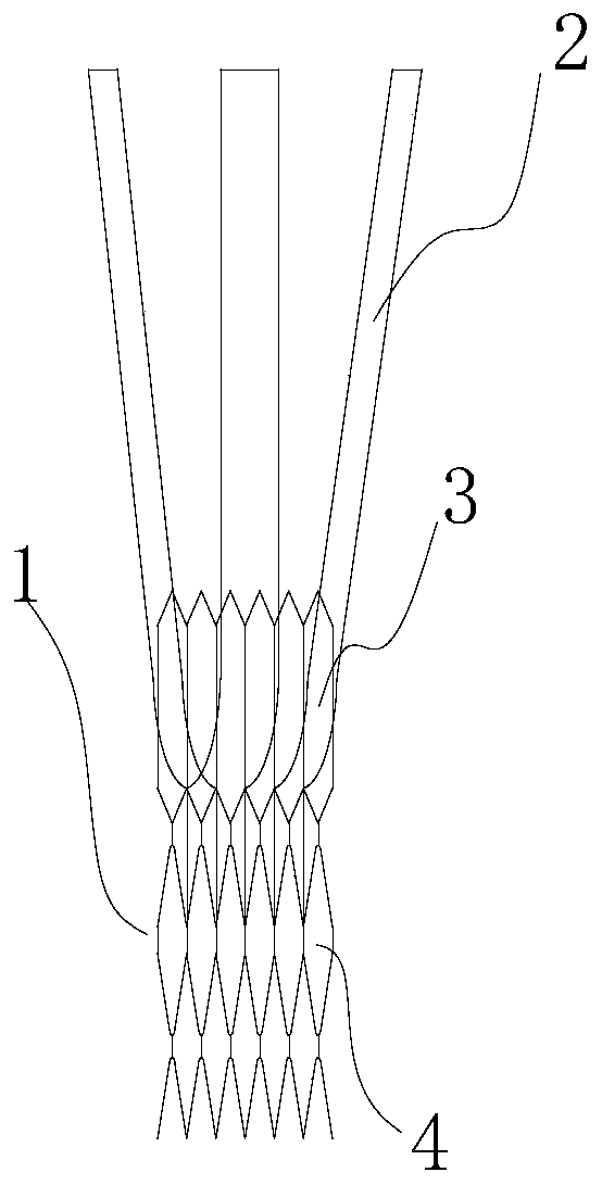
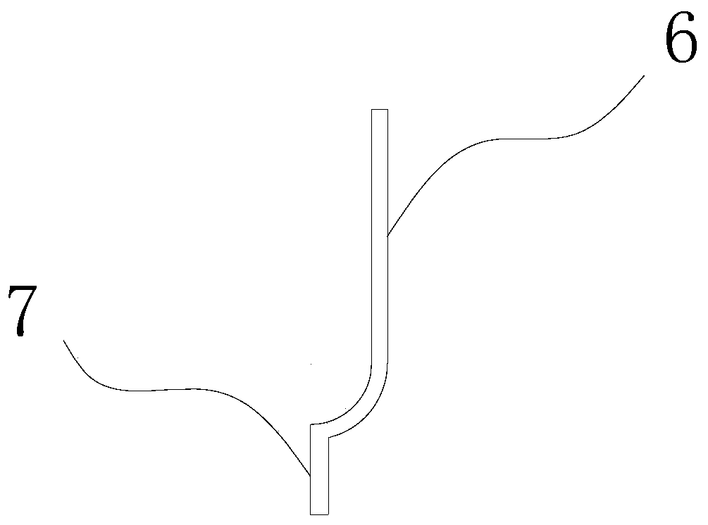
[0024] A transcatheter implanted aortic valve stent, comprising a ring-shaped bottomless grid stent 1 braided by alloy materials and an aortic valve, the ring-shaped bottomless grid stent 1 is stretched by balloon expansion, and the aortic valve The arterial valve is set in the ring-shaped bottomless grid support, and the self-expanding positioning structure 2 is arranged on the ring-shaped bottomless grid support. The self-expanding positioning structure 2 is three U-shaped columns symmetrically arranged on the ring-shaped bottomless grid support. The U-shaped cylinder is provided with an extension part 7 and a "J"-shaped curved structure 6 connected with the extension part. The ring-shaped bottomless grid support is formed by connecting two rows of meshes sequentially through metal wires 5. The first row of meshes near the aortic end is 6 mm high, the metal wires are 1 mm long, and the rear row of meshes is 5 mm high. The length of the shared side between the adjacent meshe...

Embodiment 2

[0026] The delivery device comprising the aortic valve stent described in Example 1, the aortic stent is accommodated in the sheath of the delivery device, and an inflatable balloon is provided in the sheath to expand the ring-shaped bottomless grid stent.

[0027] During use, the delivery device of the aortic valve stent slides to the aortic valve area through the guide wire of the left ventricle, and with the pulling of the sheath tube, a gradual release of the aortic valve stent is formed: the self-expanding positioning structure 2 will gradually open , so as to form a support for the unexpanded stent in the aorta, and also provide effective assistance for the doctor to adjust the position of the stent, avoid positioning difficulties caused by blood pulsation, and avoid risks caused by accidental displacement during the release of the stent. After completion, the inflation valve is opened to inflate the balloon in the delivery device, and the ring-shaped bottomless grid sten...


PUM

PropertyMeasurementUnit
Sizeaaaaaaaaaa
Heightaaaaaaaaaa
Sizeaaaaaaaaaa

Abstract

Disclosed is a transcatheter implanted aortic valve stent. The stent comprises an annular bottomless grid stent body formed by weaving an alloy material and an aortic valve, the annular bottomless grid stent body is spread through the expansion of a gasbag, the aortic valve is arranged in the annular bottomless grid stent body, and the annular bottomless grid stent body is provided with a self-expanding positioning structure. The aortic valve stent can be accurately positioned in the aorta through the positioning structure of a self-expanding zone, and meanwhile, convenience is provided for adoctor to optimize and adjust the position of the stent during an operation. The accidental displacement in the stent release process is effectively reduced, and therefore the operation safety is improved.

Description

technical field [0001] The invention belongs to the technical field of valve support for transcatheter aortic valve implantation, and in particular relates to a transcatheter implanted aortic valve support. Background technique [0002] The aortic valve is a semilunar valve located between the left ventricle and the aorta, inhibiting the flow of blood injected into the aorta back into the left ventricle, morphologically similar to the pulmonary valve. Because of its central location, the aortic valve is closely related to the various chambers and valves of the heart. Percutaneous aortic valve replacement is a brand-new minimally invasive valve replacement technology developed and adopted. The English name is Percutaneous Aortic Valve Replacement, PAVR. Because the valve is not replaced like a surgical operation, it is also called transcatheter aortic valve implantation (TVAI). Since 1992, Andersen and other scholars have successively reported animal experiments of percut...

Claims


Application Information

Patent Timeline
IPC IPC(8): A61F2/24
CPCA61F2/2412A61F2/2418A61F2/2466
Inventor 陈绍良依玛丹·榭坂
Owner 陈绍良
Learn More