
Automatic slip ring clearing device for transverse moving type roller replacing and conveying trolley

A technology of automatic cleaning and roller trolley, which is applied in the direction of removing smoke and dust, cleaning methods and utensils, cleaning methods using tools, etc., and can solve problems such as short-circuit faults of electrical equipment and short-circuits of electrical circuit connections

Inactive Publication Date: 2019-10-11
BAOSHAN IRON & STEEL CO LTD
View PDF8 Cites 0 Cited by
  • Summary
  • Abstract
  • Description
  • Claims
  • Application Information

AI Technical Summary

Problems solved by technology

[0002] For the hot rolling mill, during the work roll change process, the roll change trolley is generally used, in which a large number of carbon brushes are installed in the slip ring box in the roll change trolley as the electrical part of the whole roll change trolley The drainage medium of the power supply, every time the trolley rotates, the slip ring shaft in the slip ring box will rub against the carbon brush, and the carbon powder after friction will naturally fall into the bottom of the slip ring box. When the trolley is running, the box will inevitably Vibration will be generated along with the car. When vibrating, the toner at the bottom of the box will be vibrated, and part of the toner will adhere to the joint of the slip ring terminal block and the wire joint like dust. The insulating zone becomes a conductive path covered with carbon powder, forming a partial connection short circuit of the electrical circuit, resulting in a short circuit fault of the electrical equipment

Method used


Image

  • Automatic slip ring clearing device for transverse moving type roller replacing and conveying trolley
  • Automatic slip ring clearing device for transverse moving type roller replacing and conveying trolley
  • Automatic slip ring clearing device for transverse moving type roller replacing and conveying trolley

Examples


Embodiment Construction

[0018] The technical solutions of the present invention will be further described below in conjunction with the accompanying drawings and embodiments.

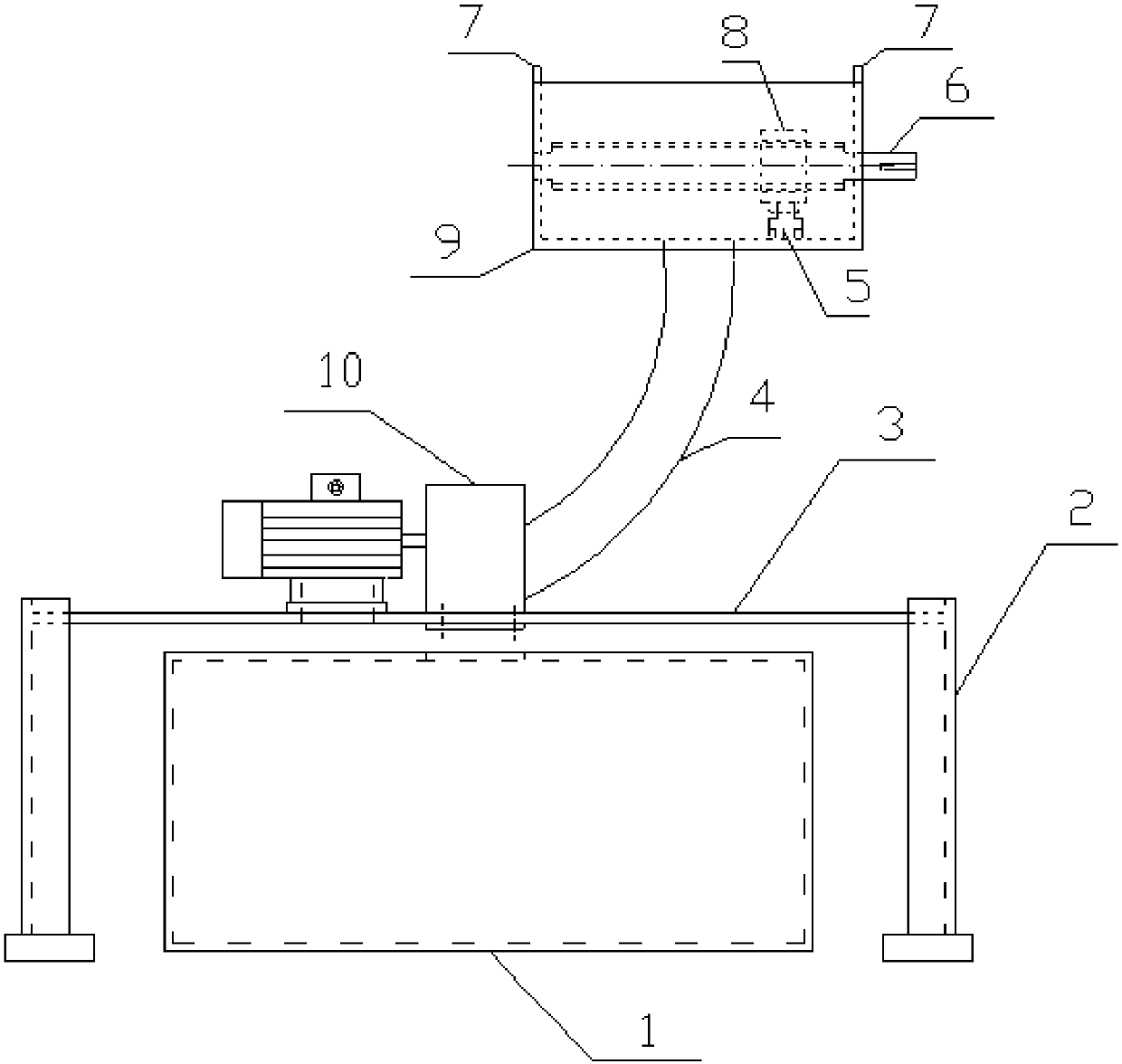
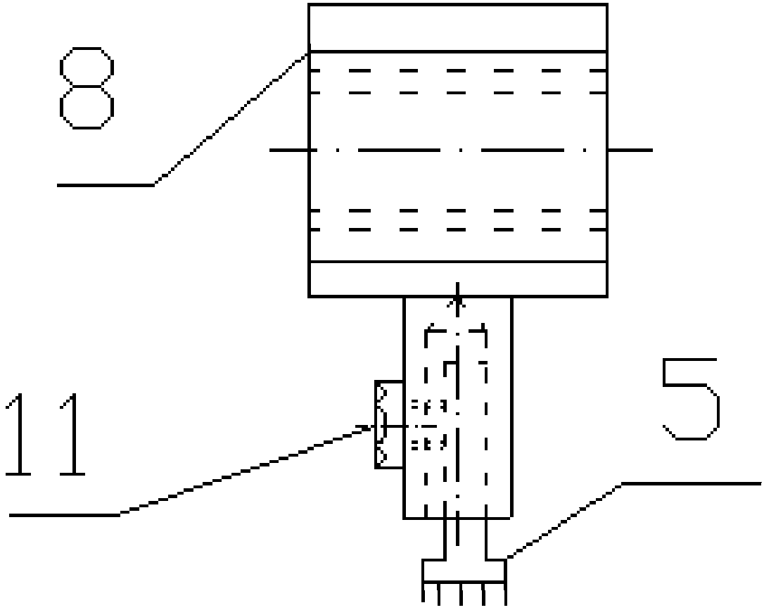
[0019] Please combine Figure 1 to Figure 4 As shown, a kind of automatic cleaning device for the slip ring of a roller-changing and roller-feeding trolley provided by the present invention includes: a toner cleaning mechanism, a toner suction mechanism and a dust storage box 1, a toner cleaning mechanism and a toner suction mechanism Connected, the dust storage box 1 is located below the toner suction mechanism.

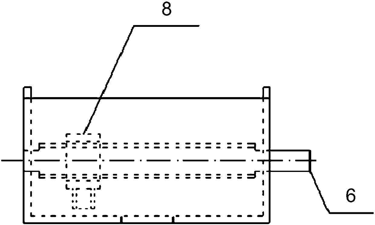
[0020] Preferably, the toner cleaning mechanism includes: a dust box 9, a drive screw 6 horizontally arranged in the dust box 9, a dust removal brush 5 connected to the drive screw 6, and the drive screw 6 is connected to an external motor.

[0021] Preferably, the toner suction mechanism includes: a dust suction pipe 4 and a dust suction device 10, one end of the dust suction pipe 4 communicates with the bottom of...


PUM


Abstract

The invention discloses an automatic slip ring clearing device for a transverse moving type roller replacing and conveying trolley. Automatic slip ring clearing device comprises a carbon powder sweeping mechanism, a carbon powder suction mechanism and a dust box. The carbon powder sweeping mechanism is connected with the carbon powder suction mechanism. The dust box is arranged below the carbon powder suction mechanism. The carbon powder sweeping mechanism comprises a dust receiving box, a transmission threaded rod horizontally arranged in the dust receiving box and a dust removing brush connected to the transmission threaded rod. The carbon powder suction mechanism comprises a dust suction pipe and a dust suction device. One end of the dust suction pipe communicates with the bottom of thedust receiving box. The other end of the dust suction pipe communicates with the dust suction device. The automatic slip ring clearing device of the transverse moving type roller replacing and conveying trolley overcomes the defects of the prior art and meets requirements on a production site.

Description

technical field [0001] The invention relates to a hot continuous finishing mill, and more specifically, relates to a horizontally moving automatic cleaning device for slip rings of a roll-changing trolley and a roll-feeding trolley. Background technique [0002] For the hot rolling mill, during the work roll change process, the roll change trolley is generally used, in which a large number of carbon brushes are installed in the slip ring box in the roll change trolley as the electrical part of the whole roll change trolley The drainage medium of the power supply, every time the trolley rotates, the slip ring shaft in the slip ring box will rub against the carbon brush, and the carbon powder after friction will naturally fall into the bottom of the slip ring box. When the trolley is running, the box will inevitably Vibration will be generated along with the car. When vibrating, the toner at the bottom of the box will be vibrated, and part of the toner will adhere to the joint...

Claims


Application Information

Patent Timeline
IPC IPC(8): B08B1/00B08B15/04B21B31/08
CPCB08B15/04B21B31/08B08B1/30B08B1/12
Inventor 郁华军王军
Owner BAOSHAN IRON & STEEL CO LTD
Learn More