Soldering iron core, soldering system and temperature control method of soldering iron

A temperature control method and a technology for soldering iron cores, which are applied in the field of soldering iron cores and can solve the problems of inability to obtain them.

Inactive Publication Date: 2019-10-11
HAKKO CO LTD
View PDF7 Cites 3 Cited by
  • Summary
  • Abstract
  • Description
  • Claims
  • Application Information

AI Technical Summary

Problems solved by technology

However, no information about the temperature of the tip and heater can be obtained from said core
The described soldering iron core has only one thermocouple arranged near the distal end of the tip, therefore, only information about the temperature of the distal end of the tip can be obtained

Method used


Image

  • Soldering iron core, soldering system and temperature control method of soldering iron
  • Soldering iron core, soldering system and temperature control method of soldering iron
  • Soldering iron core, soldering system and temperature control method of soldering iron

Examples


Embodiment Construction

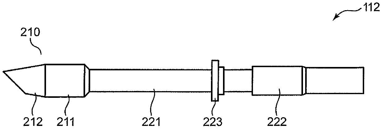
[0055] figure 1 It is a side view of the soldering iron core 112 for soldering irons. refer to figure 1 , Image 6 and Figure 11 Soldering iron core 112 will be described.

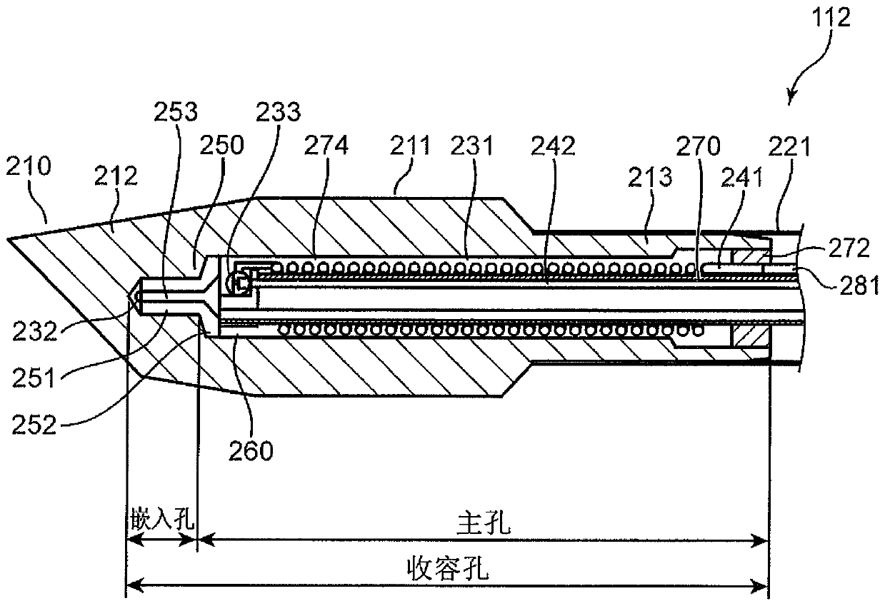
[0056] The soldering iron core 112 includes a soldering iron tip 210 at the distal end. The soldering iron core 112 further includes: a soldering iron core barrel 221 extending from the soldering iron tip 210 to the base end side; and a connector barrel 222 attached to the base end portion of the soldering iron core barrel 221 . The soldering iron core 112 has a connector assembly 280 provided in the connector barrel 222 (see Image 6 ). The space in the soldering iron core barrel 221 is used for wiring from the connector assembly 280 to the distal end side.

[0057] The connector barrel 222 of the soldering iron core 112 is securely embedded in the Figure 11 The structure of the handle 111 is shown. If the connector barrel 222 is inserted into the handle 111, the soldering iron core 112 and the...


PUM


Abstract

The invention provides a soldering iron core, a soldering system and a temperature control method of the soldering iron. The soldering iron core includes: a soldering iron tip; a heater disposed in the soldering iron tip for heating the soldering iron tip; a first sensor disposed in the soldering iron tip for detecting the temperature of the soldering iron tip ; and a second sensor disposed in thesoldering iron tip so as to be closer to the heater than the first sensor for detecting the temperature of the heater. Accordingly, the temperatures of the heater and the tip can be individually detected.

Description

technical field [0001] The invention relates to a soldering iron core for soldering iron, a soldering system and a temperature control method of the soldering iron. Background technique [0002] Various soldering irons used for soldering work have been developed (refer to Patent Document 1). Patent Document 1 discloses a soldering iron of a soldering iron core type. The soldering iron core of the soldering iron has a soldering iron tip, a thermocouple arranged in the soldering iron tip, and a heater for heating the soldering iron tip in the soldering iron tip. [0003] If the temperature difference between the heater and the soldering iron tip is large, the amount of heat transferred from the heater to the soldering iron tip is large. On the other hand, if the temperature difference between them is small, the amount of heat transferred from the heater to the tip of the soldering iron becomes small. Therefore, the temperature relationship between them is related to the amo...

Claims


Application Information

Patent Timeline
Patent Type & Authority Applications(China)
IPC IPC(8): B23K3/03B23K3/08
CPCB23K3/03B23K3/033B23K3/08B23K3/0353B23K3/0478B23K3/053
Inventor 望月俊和竹内仁志宫原光司
Owner HAKKO CO LTD
Why Eureka
Try Eureka