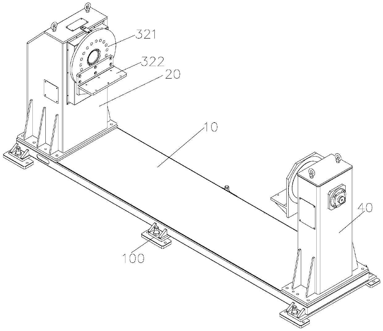
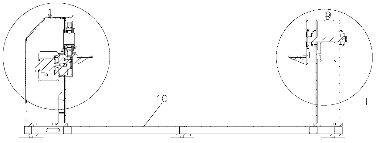
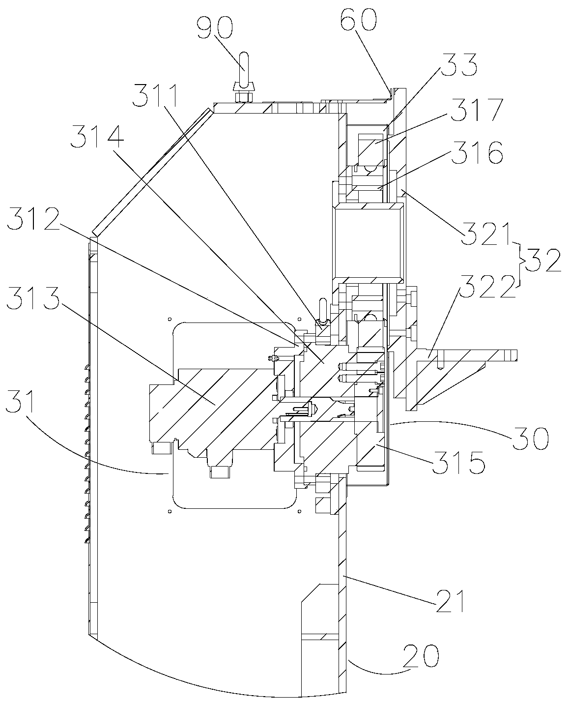
Positioner and welding device

A positioner and connector technology, applied in auxiliary devices, welding equipment, auxiliary welding equipment and other directions, can solve the problems of low production efficiency of chassis frame welding, and achieve the requirements of satisfying welding reliability, improving welding quality and reducing production costs. Effect

Inactive Publication Date: 2019-10-11
ZHUHAI GREE INTELLIGENT EQUIP CO LTD +1
View PDF5 Cites 7 Cited by
  • Summary
  • Abstract
  • Description
  • Claims
  • Application Information

AI Technical Summary

Problems solved by technology

[0003] The main purpose of the present invention is to provide a positioner and a welding device to solve the problem of low production efficiency of chassis frame welding in the prior art

Method used


Image

  • Positioner and welding device
  • Positioner and welding device
  • Positioner and welding device

Examples


Embodiment Construction

[0023] It should be noted that, in the case of no conflict, the embodiments in the present application and the features in the embodiments can be combined with each other. The present invention will be described in detail below with reference to the accompanying drawings and examples.

[0024] It should be noted that the terminology used here is only for describing specific implementations, and is not intended to limit the exemplary implementations according to the present application. As used herein, unless the context clearly dictates otherwise, the singular is intended to include the plural, and it should also be understood that when the terms "comprising" and / or "comprising" are used in this specification, they mean There are features, steps, operations, means, components and / or combinations thereof.

[0025] For the convenience of description, spatially relative terms may be used here, such as "on ...", "over ...", "on the surface of ...", "above", etc., to describe the ...


PUM


Abstract

The invention provides a positioner and a welding device. The positioner comprises a bottom frame, a first support mechanism, a driving mechanism, a second support mechanism, a driven mechanism and abearing frame. The first support mechanism is arranged at the first end of the bottom frame. The driving mechanism comprises a driving assembly and a first connection assembly, is installed on the first support mechanism and is in driving connection with the first connection assembly. The second support mechanism is installed at the second end, opposite to the first end, of the bottom frame. The driven mechanism comprises a rotary structure and a second connection assembly connected with the rotary structure. The two ends of the bearing frame are fixedly connected with the first connection assembly and the second connection assembly correspondingly. According to the positioner and the welding device, production cost of a chassis support is lowered, the number of times of clamping of the chassis support is reduced with the positioner, the positioner drives the chassis support to overturn, thus almost all weld joints can be welded, production efficiency is improved, and labor intensity is relieved.

Description

technical field [0001] The invention relates to the technical field of welding equipment, in particular to a positioner and a welding device. Background technique [0002] In the past, the chassis frame was fixed on the workbench with ordinary elbow clamps for welding. In this way, only the front side can be welded, and the reverse side must be flipped and clamped again. The welding process cannot be selected for the product weld seam, and there is little room for welding quality adjustment. If the frame is large, if it is only fixed on the workbench for welding, the working range of the welding robot needs to be relatively large. In that case, it is necessary to choose a relatively large robot, or use some more complicated structures to install the welding robot upside down to meet the working range. The welding production efficiency of the chassis frame is low, the welding quality is poor, the labor intensity is high, and the equipment cost is high, so it is difficult to m...

Claims


Application Information

Patent Timeline
Patent Type & Authority Applications(China)
IPC IPC(8): B23K37/047
CPCB23K37/047
Inventor 郭荣忠谭华泰胡为纬张勇卢中伟
Owner ZHUHAI GREE INTELLIGENT EQUIP CO LTD
Why Eureka
Try Eureka