Propeller machining technology

A processing technology and propeller technology, applied in the directions of propellers, rotary propellers, rotary propellers, etc., can solve the problems of high production cost, time-consuming and laborious processing, etc., and achieve the effect of reducing processing time and production cost.

Active Publication Date: 2019-10-11
重庆市万州区腾伟机械有限公司
View PDF9 Cites 4 Cited by
  • Summary
  • Abstract
  • Description
  • Claims
  • Application Information

AI Technical Summary

Problems solved by technology

The traditional propeller processing technology needs multiple processes such as scribing the helix line after correcting the blank, and removing the excess allowance after measuring the machining allowance. Time-consuming and labor-intensive, high production cost

Method used


Image

  • Propeller machining technology
  • Propeller machining technology
  • Propeller machining technology

Examples


Embodiment Construction

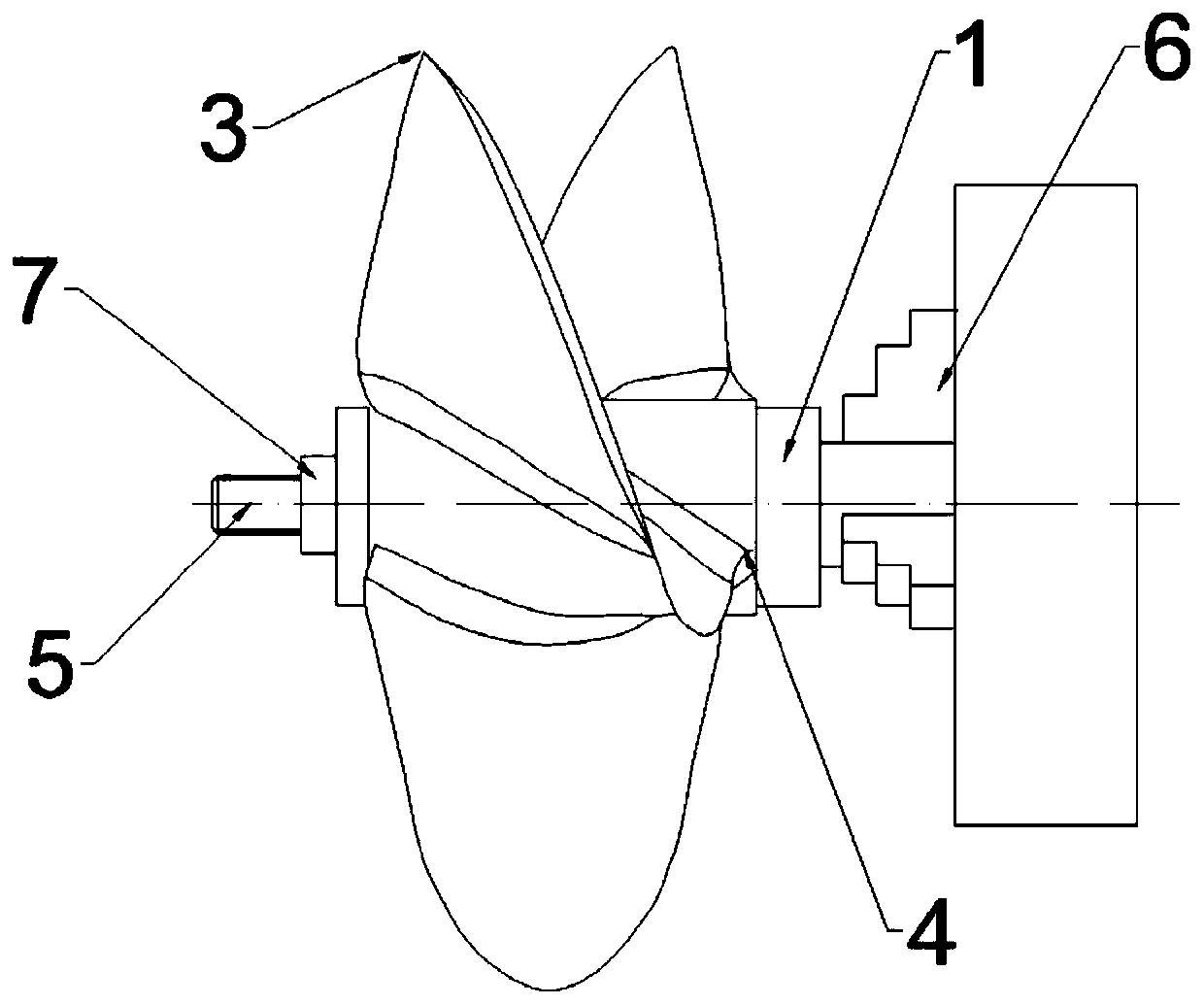
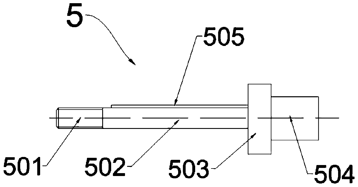
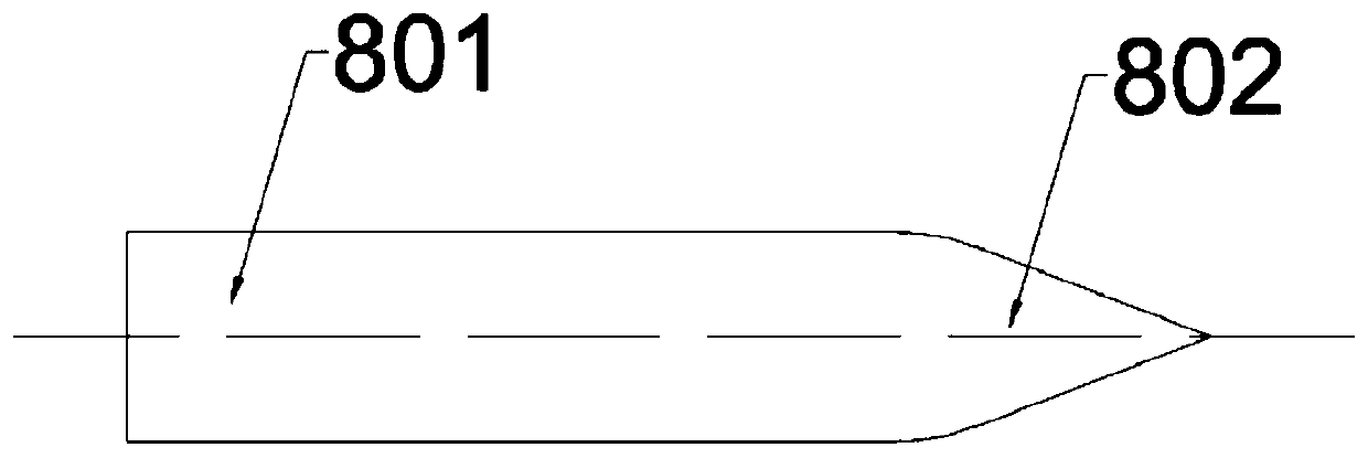
[0029] figure 1 Is a schematic diagram of the structure of the present invention, figure 2 Is a schematic diagram of the structure of the mandrel of the present invention, image 3 Is a schematic diagram of the structure of the scribing tool of the present invention, Figure 4 The schematic diagram of the propeller. Such as Figure 1-Figure 4 As shown, the manufacturing process of the propeller in this embodiment includes the following steps:

[0030] S1, blank production;

[0031] S2. Use a milling machine to process the front and rear ends of the blank propeller hub 1;

[0032] S3. Use a boring machine to process the central through hole 2 of the propeller hub 1;

[0033] S4. Use a slotting machine to machine a keyway 201 along the radial direction of the through hole 2;

[0034] S5. Mount the blank processed in S4 on the fixture, and then clamp the fixture on the four-axis machining center;

[0035] S6. Move the scribing tool to the middle of the tip 3 of the blank propeller blade ...


PUM


Abstract

The invention discloses a propeller machining technology. According to the propeller machining technology, a four-axis machining center presets a movement path of a marking knife, and according to comparison of the thicknesses of the outer contours of a blank blade on the two sides of the movement path of the marking knife, whether the position of the marking knife is right or not is judged; afterthe position of the marking knife is centered, the null position of the four-axis machining center is determined, with the intersection point between the axis of a center through hole of a propellerhub and the front end face of the propeller hub at the moment as the null point, blade backs and blade faces of all the propeller blades are sequentially machined; during machining, marking on each blade of the blank is not needed, so that the machining time is greatly shortened, and production cost is lowered.

Description

Technical field [0001] The invention relates to the technical field of mechanical processing, in particular to a propeller processing technology. Background technique [0002] Propeller refers to a device that relies on blades to rotate in air or water to convert engine rotational power into propulsion. There may be two or more blades connected to the hub. Traditional propeller processing technology requires multiple processes such as scribing the spiral line after correcting the blank, measuring the machining allowance and removing the excess allowance, and each blade of the propeller blank needs to be scribed and the machining allowance removed. Time-consuming, laborious, and high production cost. [0003] Therefore, in order to solve the above problems, a propeller machining process is needed, which can preset the scribing tool movement path through the four-axis machining center, and judge the scribing based on the comparison of the scribing tool movement path and the thicknes...

Claims


Application Information

Patent Timeline
Patent Type & Authority Applications(China)
IPC IPC(8): B23P15/00B63H1/14B64C11/00
CPCB23P15/00B63H1/14B64C11/00
Inventor 易良培李质平
Owner 重庆市万州区腾伟机械有限公司
Why Eureka
Try Eureka