Supercharge Your Innovation With Domain-Expert AI Agents!

Pantograph insulation bow angle and pantograph

A pantograph and angle end technology, applied in the field of mechanical structure, can solve the problems of high cost of new manufacture and maintenance, non-wear-resistant bow angle, discharge at the bottom of the bow angle, etc., to reduce the cost of new manufacture and maintenance, good manufacturability, and convenient use Effect

Active Publication Date: 2021-02-12
BEIJING CED RAILWAY ELECTRIC TECH
View PDF6 Cites 0 Cited by
  • Summary
  • Abstract
  • Description
  • Claims
  • Application Information

AI Technical Summary

Problems solved by technology

[0006] At present, the bow angle of the pantograph is usually made of metal circular pipe. When the bow is in the bow position, the distance between the bottom of the bow angle and the roof is often the lowest point of the electrical clearance. discharge phenomenon
[0007] In another existing technology, in order to prevent partial discharge, the first thing that comes to mind is to use non-metallic insulating material for the bow angle as a whole, but after a period of application, it is found that the bow angle of this technical solution is not wear-resistant, easy to crack, and difficult to Disadvantages such as weight loss, high cost of new construction and maintenance

Method used


Image

  • Pantograph insulation bow angle and pantograph
  • Pantograph insulation bow angle and pantograph
  • Pantograph insulation bow angle and pantograph

Examples


Embodiment 1

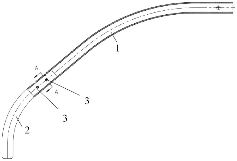
[0029] Such as figure 1 As shown, an insulating pantograph horn includes a metal bow horn main body 1 and a non-metallic bow horn end 2; the metal bow horn main body 1 is connected to the body of the pantograph, and the non-metallic bow horn end 2 and the metal bow horn The main body 1 is fixedly connected; the metal bow horn main body 1 is made of pipe material; specifically, the metal bow horn main body 1 is made of titanium alloy pipe material. While ensuring the strength and hardness, the lightweight design is conducive to the stability of pantograph-catenary flow. The non-metallic bow angle end 2 is made of a solid rod, and the non-metallic bow angle end 2 can be made of non-metallic materials with a certain strength, such as epoxy glass fiber and epoxy resin.

[0030] Here, the outer diameters of the metal bow horn main body 1 and the non-metal bow horn end 2 are the same, which meet normal use requirements.

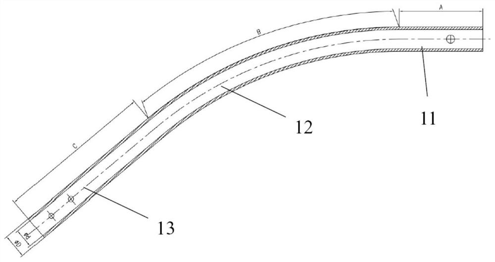
[0031] Such as figure 2 As shown, the metal bow angle mai...

Embodiment 2

[0036] Such as Figure 5 As shown, a pantograph, the two ends of the body of the pantograph are symmetrically provided with the pantograph insulating bow angles described in the first embodiment. Specifically, the pantograph insulation bow angle is connected to the bow head shaft of the pantograph body. In the bow position, the minimum space distance H1 between the pantograph insulation bow angle and the roof should meet the minimum electrical clearance specified in the standard. Requirements; At the same time, after the pantograph insulation bow angle is installed on the pantograph, the bow head height H2 and the bow head length L should meet the vehicle limit requirements.


PUM


Abstract

The invention discloses a pantograph insulation pantograph corner. The pantograph insulation pantograph corner is applied to pantograph, and comprises a metal pantograph corner main body (1) and a non-metal pantograph corner end head (2); the metal pantograph corner main body (1) is connected with a body of the pantograph; the non-metal pantograph corner end head (2) is fixedly connected with themetal pantograph corner main body (1); the metal pantograph corner main body (1) is made of a pipe; the non-metal pantograph corner end head (2) adopts a solid bar material, and the outer diameters ofthe metal pantograph corner main body (1) and the non-metal pantograph corner end head (2) are the same. According to the pantograph insulation pantograph corner, the structure is simple, the use isconvenient, the metal pantograph corner scheme and the non-metal insulation pantograph corner scheme are combined, the actual application is met, and meanwhile, the new manufacturing and overhauling cost is reduced.

Description

technical field [0001] The invention relates to the technical field of mechanical structures, in particular to an insulating bow angle of a high-speed pantograph and a pantograph. Background technique [0002] Two bow angles are symmetrically arranged on the left and right sides of the bow head of the pantograph, mainly to prevent the catenary from drilling under the bow head of the pantograph to damage the catenary or pantograph when the vehicle is running, causing pantograph-catenary accidents. Therefore, the following three factors are mainly considered in the design of the bow angle: [0003] 1) The outline of the bow head (bow angle length and height) must meet the limit requirements; [0004] 2) The strength and hardness of the bow angle must bear the pantograph-catenary load requirements; [0005] 3) Lightweight design, which is especially important for high-speed pantographs. [0006] At present, the bow angle of the pantograph is usually made of metal circular pi...

Claims


Application Information

Patent Timeline
Patent Type & Authority Patents(China)
IPC IPC(8): B60L5/20
CPCB60L5/20
Inventor 于金朋黄思俊张东远徐玉峰
Owner BEIJING CED RAILWAY ELECTRIC TECH
Features
  • R&D
  • Intellectual Property
  • Life Sciences
  • Materials
  • Tech Scout
  • Unparalleled Data Quality
  • Higher Quality Content
  • 60% Fewer Hallucinations
Learn More