
Layout and control method of distributed power tilt-wing aircraft

A technology of tilting a wing and a control method, applied in the aviation field, can solve problems such as the reliability of aerodynamic interference mode conversion control, and achieve the effects of light weight, direct and reliable control, and reduced load

Active Publication Date: 2019-10-11
BEIHANG UNIV
View PDF4 Cites 14 Cited by
  • Summary
  • Abstract
  • Description
  • Claims
  • Application Information

AI Technical Summary

Problems solved by technology

[0006] The purpose of the present invention is to provide a layout and control method of a distributed power tilting wing aircraft, to solve the problem of aerodynamic interference between the rotor and the wing and the problem of the reliability of the mode conversion control. The excellent controllability of the propulsion system and the vertical take-off and landing capability of the tilting wing aircraft are well combined to form a brand-new model scheme.

Method used


Image

  • Layout and control method of distributed power tilt-wing aircraft
  • Layout and control method of distributed power tilt-wing aircraft
  • Layout and control method of distributed power tilt-wing aircraft

Examples


Embodiment Construction

[0052] The present invention will be described in further detail below in conjunction with the accompanying drawings. These drawings are all simplified schematic diagrams, which only illustrate the basic structure of the present invention in a schematic manner, so they only show the configurations related to the present invention.

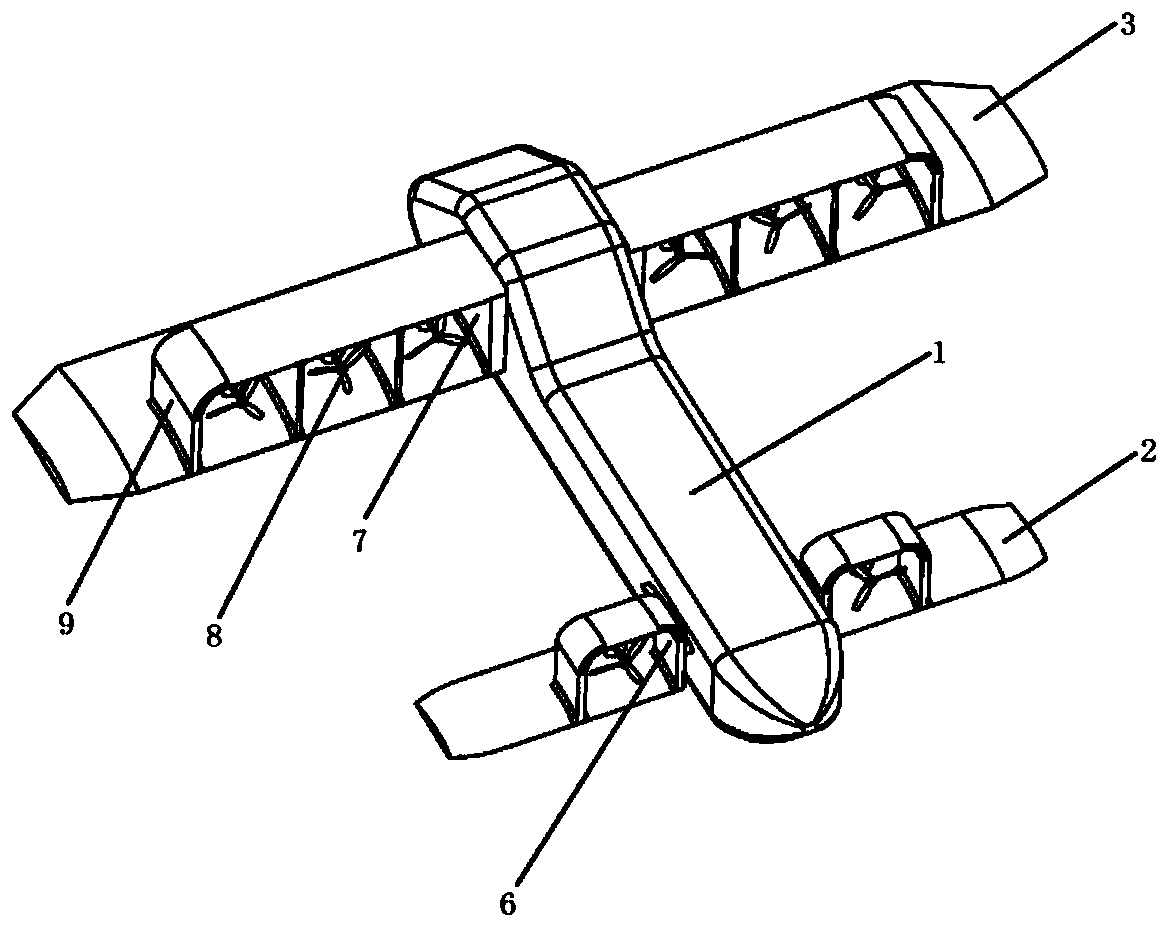
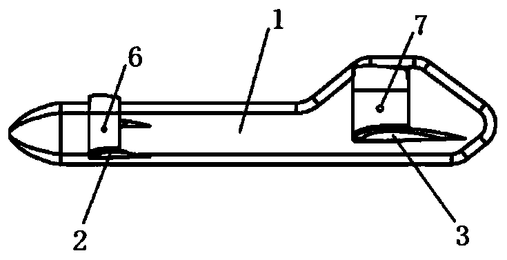
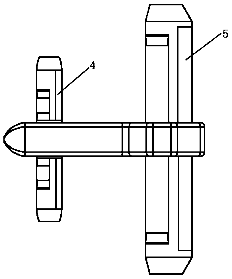
[0053] As shown in Figure 1, a layout of a distributed power tilting wing aircraft includes a fuselage 1, a front canard 2, a wing main wing 3, a front canard elevator 4, a wing aileron 5, and a forward tilting shaft 6. Rear tilt shaft 7, power system 8, vertical stabilizer 9.

[0054] The fuselage 1 is the main load-carrying part of the effective transport load of the aircraft, and plays the role of connecting various parts; Wing 5 provides the steering moment in level flight, the front canard elevator 4 provides the pitching moment, and the wing aileron 5 provides the rolling moment; the forward-tilt shaft 6 and the rear-tilt shaft 7 connect the...


PUM


Abstract

The invention discloses a layout and control method of a distributed power tilt-wing aircraft. A canard-configuration aircraft is selected. Channels are disposed inside a front canard wing and a mainwing for mounting a plurality of engines to realize distributed power. For a vertical take-off state, the front canard wing and the main wing are tilted to be vertical, eight engines generate a pulling force to enable engine bodies off from the ground, and meanwhile, a differential operation is performed for correcting the attitude of the engine bodies. Upon reaching a certain height, the front canard wing and the main wing gradually tilt, and an angle is dynamically adjusted according to an accelerator. When a current forward speed is sufficient to make a lifting force generated by the frontcanard wing and the main wing balanced against gravity, the front canard wing and the main wing completely turn to be horizontal, and enter a high-speed flat flying state, such that the transition from vertical take-off to hovering to flat flying is realized. The transition process from flat flying to hovering to vertical landing is just opposite. The power system of the invention is disposed simply and a latching mechanism is disposed. The control of the invention is direct and reliable and isolates a tilting mechanism from attitude control, thereby avoiding the problem of causing failure ofa plurality of functions by a system fault.

Description

technical field [0001] The present invention relates to a layout and control method of a distributed power tilting wing aircraft, and relates to a layout scheme of a vertical take-off and landing aircraft based on tilting wing technology and its modes of vertical take-off and landing, hovering, and level flight. and the control method for switching between modes. It belongs to the field of aviation technology. Background technique [0002] In recent years, vertical take-off and landing aircraft is very popular in both military and civilian fields. After the U.S. wars against Iraq and Afghanistan ended, the U.S. paid more and more attention to the development of vertical take-off and landing aircraft, and gave it the top ten categories of future key equipment for the U.S. military. Its ability to adapt to complex terrain and environments is what the US military values. The rest of the countries are also catching up with the pace of the United States, putting more energy in...

Claims


Application Information

Patent Timeline
IPC IPC(8): B64C29/00B64C27/26B64C27/28
CPCB64C27/26B64C27/28B64C29/0033
Inventor 周尧明苏雨赵浩然陈旭智
Owner BEIHANG UNIV
Learn More