
An outdoor loudspeaker protective box

A loudspeaker and protective box technology, applied in the field of loudspeakers, can solve the problems of lack of protective measures, loudspeaker's fragile life, and inconvenient transportation, so as to achieve the effect of being convenient to use in outdoor environments, conducive to carrying and use, and preventing displacement

Active Publication Date: 2021-03-23
王一妃
View PDF7 Cites 0 Cited by
  • Summary
  • Abstract
  • Description
  • Claims
  • Application Information

AI Technical Summary

Problems solved by technology

[0003] Some loudspeakers used outdoors are large in size, inconvenient to carry, and easy to be damaged by collision during the handling process; moreover, outdoor speakers are used in a poor environment, and generally lack necessary protection measures against the sun and rain, resulting in easy damage to the speakers or shortened service life

Method used


Image

  • An outdoor loudspeaker protective box
  • An outdoor loudspeaker protective box
  • An outdoor loudspeaker protective box

Examples


Embodiment 1

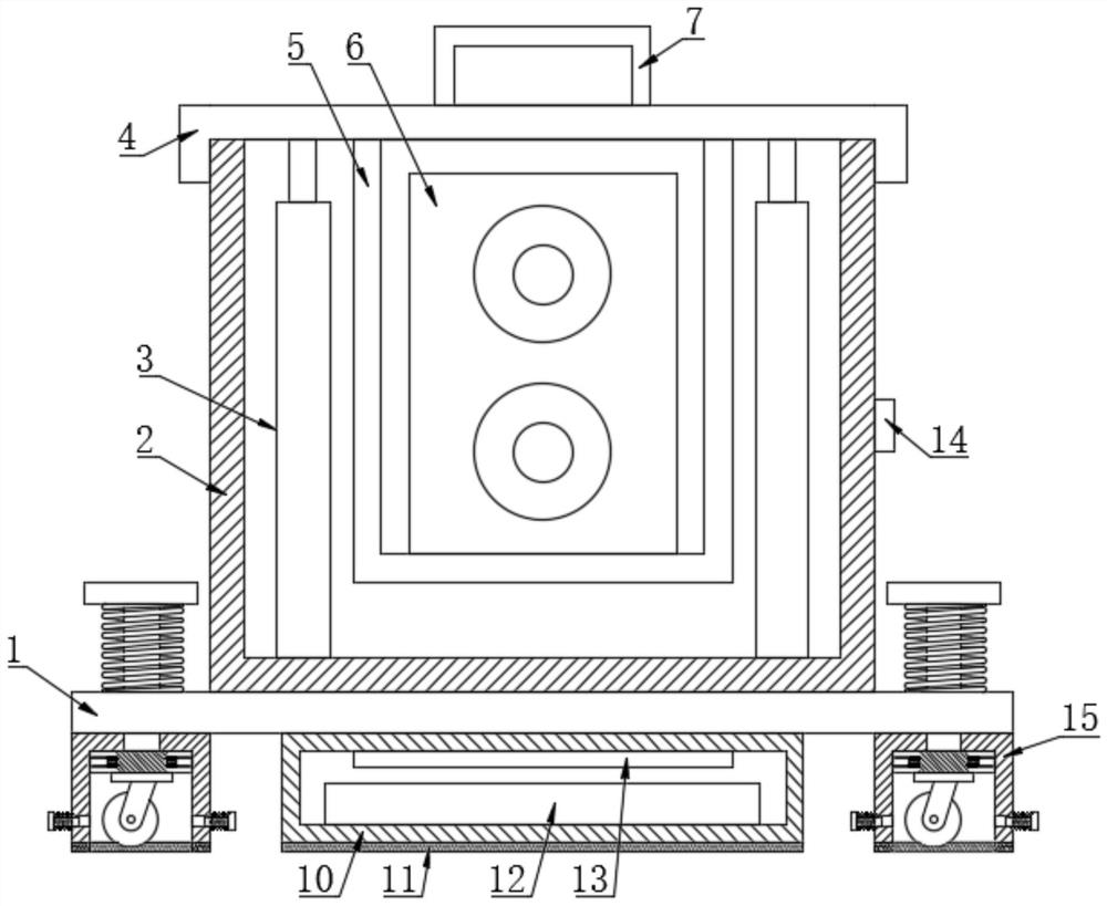
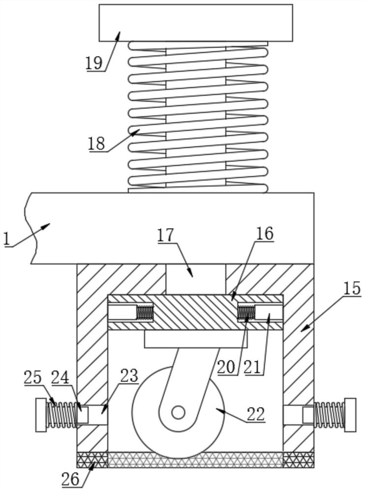
[0024] see Figure 1~2 , an outdoor loudspeaker protective box, comprising a base 1, a box body 2 is fixedly arranged on the top of the base 1, and electric push rods 3 are fixedly arranged on the left and right sides of the inner bottom of the box body 2, and the top of the electric push rod 3 is fixed Connected with the upper cover 4 that cooperates with the box body 2, the bottom of the upper cover 4 is fixedly connected with a U-shaped plate 5, and a loudspeaker 6 is fixedly arranged in the U-shaped plate 5. When the loudspeaker 6 is used, the push rod 3 of the electric push rod is controlled to extend The loudspeaker 6 can be stretched out of the box body 2 when it is long, and the protection of the upper cover 4 can play the role of sunshade and rain. The body 2 is protected to avoid collisions during moving and handling; the top of the upper cover 4 is fixedly connected with a handle 7, and the box body 2 is conveniently lifted through the handle 7; the bottom of the ba...

Embodiment 2

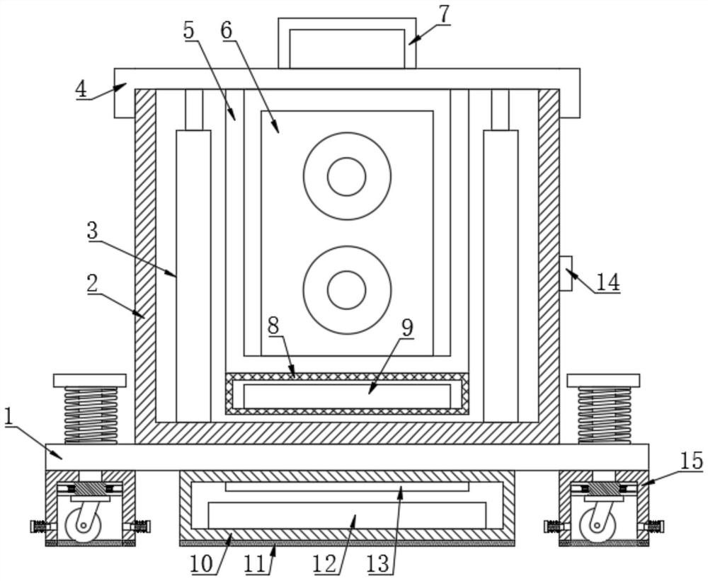
[0027] see Figure 3-5 , on the basis of Example 1, the bottom of the U-shaped plate 5 is also fixedly connected with a drying box 8, and a desiccant 9 is placed in the drying box 8, and the drying box 8 is made of a mesh plate, and the shrinking drying box 8. The front wall is open, and the desiccant 9 is easy to replace; when it is used in rainy days, the air is relatively humid. When the speaker 6 is not in use, the inside of the cabinet 2 is dried through the desiccant 9 to ensure that the speaker 6 is in a dry environment, and prevent the humid air from affecting the life of the speaker 6. .

[0028] An outdoor broadcasting system includes the above-mentioned outdoor loudspeaker protective box.


PUM


Abstract

The invention relates to the technical field of loudspeakers and discloses an outdoor loudspeaker protection box which comprises a base. A box body is fixedly arranged at the top of the base. Electricpush rods are fixedly arranged on the left side and the right side of the bottom in the box body respectively. The top ends of the electric push rods are fixedly connected with an upper cover matchedwith the box body. The bottom of the upper cover is fixedly connected with a U-shaped plate, and a loudspeaker is fixedly arranged in the U-shaped plate. Supporting legs are further fixedly connectedto the four corners of the bottom of the base. Cavities are formed in the bottoms of the supporting legs. Lifting plates are arranged in the cavities. Universal wheels are fixedly installed at the bottoms of the lifting plates, and guide rods are fixedly connected to the tops of the lifting plates, penetrate through the supporting legs and the base and are in sliding connection with the supporting legs and the base. Round grooves are formed in the left side wall and the right side wall of the lifting plate, and positioning pins are fixedly connected into the round grooves through second springs. The box body is used for protection so that collision in the moving and carrying process is avoided. Sun-shading and rain-shielding effects can be achieved through protection of the upper cover, and the box is conveniently used outdoors.

Description

technical field [0001] The invention relates to the technical field of loudspeakers, in particular to an outdoor loudspeaker protective box. Background technique [0002] The loudspeaker is also called "horn". It is a transducer device that converts electrical signals into acoustic signals. The performance of the speaker has a great influence on the sound quality. The audio power passes through electromagnetic, piezoelectric or electrostatic effects to make its paper cone or diaphragm vibrate and interact with the surrounding environment. The air resonates and emits sound. Usually, multimedia speakers are designed with two-unit two-way frequency. One smaller speaker is responsible for the output of the mid-high frequency, while the other larger speaker is responsible for the output of the mid-bass. The tweeter of the multimedia active speaker Now the soft dome is the main one, which can reduce the rigidity of high-frequency signals and give people a soft, smooth and delicat...

Claims


Application Information

Patent Timeline
Patent Type & Authority Patents(China)
IPC IPC(8): H04R1/02
CPCH04R1/02
Inventor 王一妃
Owner 王一妃
Learn More