
Methods and device for monitoring a beam guiding optical unit in a laser processing head during laser material processing

A laser processing head and optical device technology, which is applied in laser welding equipment, metal processing equipment, welding equipment, etc., can solve problems such as damage to optical devices, and achieve the effect of compact structure and improved reliability

Active Publication Date: 2019-10-11
PRECITEC GMBH
View PDF10 Cites 0 Cited by
  • Summary
  • Abstract
  • Description
  • Claims
  • Application Information

AI Technical Summary

Problems solved by technology

[0008] In the prior art, although focus position monitoring for focus position compensation can also be carried out in the case of high contamination levels, there is, however, the risk of complete destruction of the contaminated optics, since the contamination is not detected

Method used


Image

  • Methods and device for monitoring a beam guiding optical unit in a laser processing head during laser material processing
  • Methods and device for monitoring a beam guiding optical unit in a laser processing head during laser material processing
  • Methods and device for monitoring a beam guiding optical unit in a laser processing head during laser material processing

Examples


Embodiment Construction

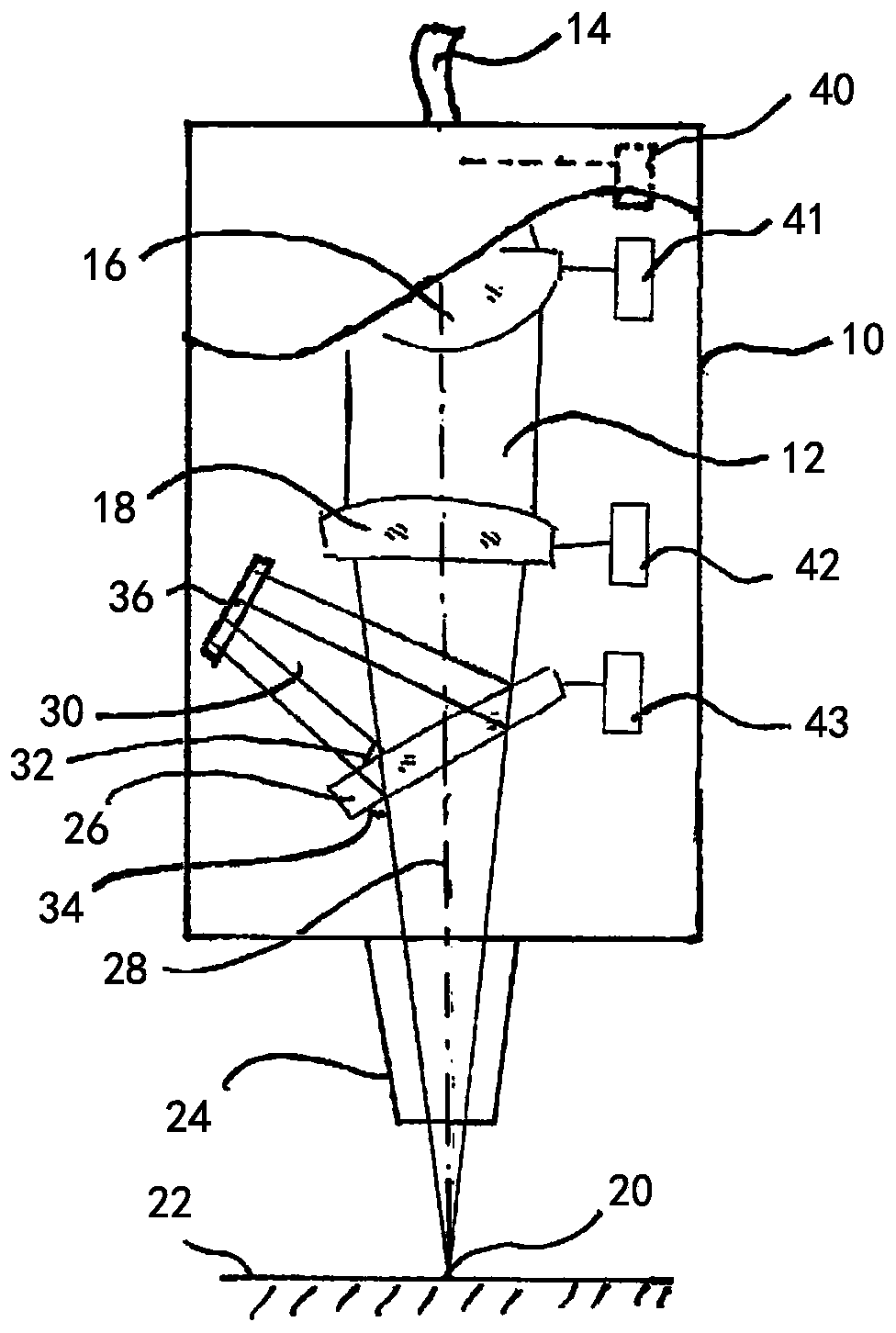
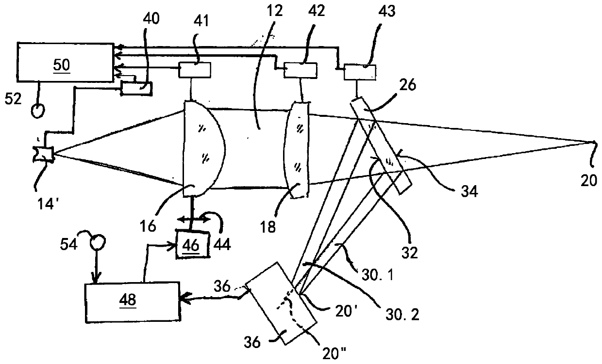
[0036] figure 1 The laser processing head 10 is schematically shown, through which the processing laser beam 12 is guided. This processing laser is supplied to the laser processing head 10 via the optical fiber 14, for example. The processing laser beam 12 emitted from the optical fiber 14 is collimated by the first optical device 16 and focused by the focusing optical device 18 into the laser focus 20 on the workpiece 22. A protective glass 26 is usually arranged between the focusing optics 18 and the beam nozzle 24 through which the converged processing laser beam 12 is focused on the workpiece 22, which should protect the interior of the laser processing head and especially The focusing optics 18 is protected from contamination, which may be caused by spatter or dense smoke, for example.

[0037] The first optics 16 and the focusing optics 18 are shown as a single lens, but may also be known as a lens group. The first optics 16 can in particular consist of a movable lens of ...


PUM


Abstract

The invention relates to methods and a device for monitoring a beam guiding optical unit in a laser processing head (10) during laser material processing, wherein a physical parameter of at least oneoptical element (16, 18, 26) of the beam guiding optical unit, which parameter correlates with the degree of contamination of the at least one optical element, is measured during the laser material processing, the current focus position is detected for focal position regulation by a spatially resolving sensor (36), which measures the beam diameter in the region of the focus (20), and an evaluationcircuit (48) determines the current focus position from the output signal of the spatially resolving sensor (36) and outputs an actuating signal for an actuating drive, which displaces at least one optical element (16; 18; 26) of the beam guiding optical unit for focal position correction, wherein a measured focal position change is compensated for as long as the measured value of the physical parameter of the at least one optical element (16, 18, 26) of the beam guiding optical unit has not yet reached an assigned critical value, and an error signal is output if the measured parameter valueof the at least one optical element (16; 18; 26) of the beam guiding optical unit reaches the assigned critical value.

Description

Technical field [0001] The invention relates to a method and a device for monitoring beam guiding optics in a laser processing head and adjusting the focus position during laser material processing. Background technique [0002] The problem in laser material processing is the so-called "thermal lens", which can be attributed to the heating of the optical elements used for laser beam guidance and focusing due to the laser power, especially the laser power in the range of several kilowatts. Due to the temperature dependence of the refractive index of the optical glass. The thermal lens causes the focal point to shift along the beam propagation direction during laser material processing. [0003] During the laser material processing process, two mechanisms that cause optical components to heat up first appear. The reason for this is the increase in laser power on the one hand, and the contamination of optical components on the other hand. In addition, it is possible that the optica...

Claims


Application Information

Patent Timeline
Patent Type & Authority Applications(China)
IPC IPC(8): B23K26/70B23K26/046
CPCB23K26/046B23K26/707B23K26/705B23K26/032
Inventor D·布拉斯奎兹-桑切斯N·韦肯曼
Owner PRECITEC GMBH
Learn More