Automatic intubating machine

An intubation machine and automatic technology, applied in metal processing, metal processing equipment, manufacturing tools, etc., can solve the problems of low intubation efficiency, difficulty in handling, and non-rebound connection tubes, so as to ensure the movement track and improve the intubation. Good pipe efficiency and guiding performance

Pending Publication Date: 2019-10-15
AUTOBIO LABTEC INSTR CO LTD
View PDF0 Cites 1 Cited by
  • Summary
  • Abstract
  • Description
  • Claims
  • Application Information

AI Technical Summary

Problems solved by technology

[0003] The traditional intubation method is to manually insert the connecting tube and the connector into one body. When the force of both hands exceeds 0.7kg during insertion, the operator will experience hand fatigue. However, when the connector and the connecting tube are inserted, 0.9 kg is required. ~1.9kg of external force, so manual intubation is likely to cause hand fatigue and low intubation efficiency. At the same time, due to the smooth surface and small size of the joint, it is difficult to intubate, and it is easy to slip during insertion, resulting in joint breakage or accidental injury to the operator
Therefore, at present, in manual intubation, heating and softening the connecting tube or spraying alcohol is usually used to reduce the intubation force, but softening the connecting tube or spraying alcohol is still difficult to handle, and the softened connecting tube is prone to non-rebounding of the connecting tube Phenomenon, affecting the sealing performance of joints and connecting pipes

Method used


Image

  • Automatic intubating machine
  • Automatic intubating machine
  • Automatic intubating machine

Examples


Embodiment Construction

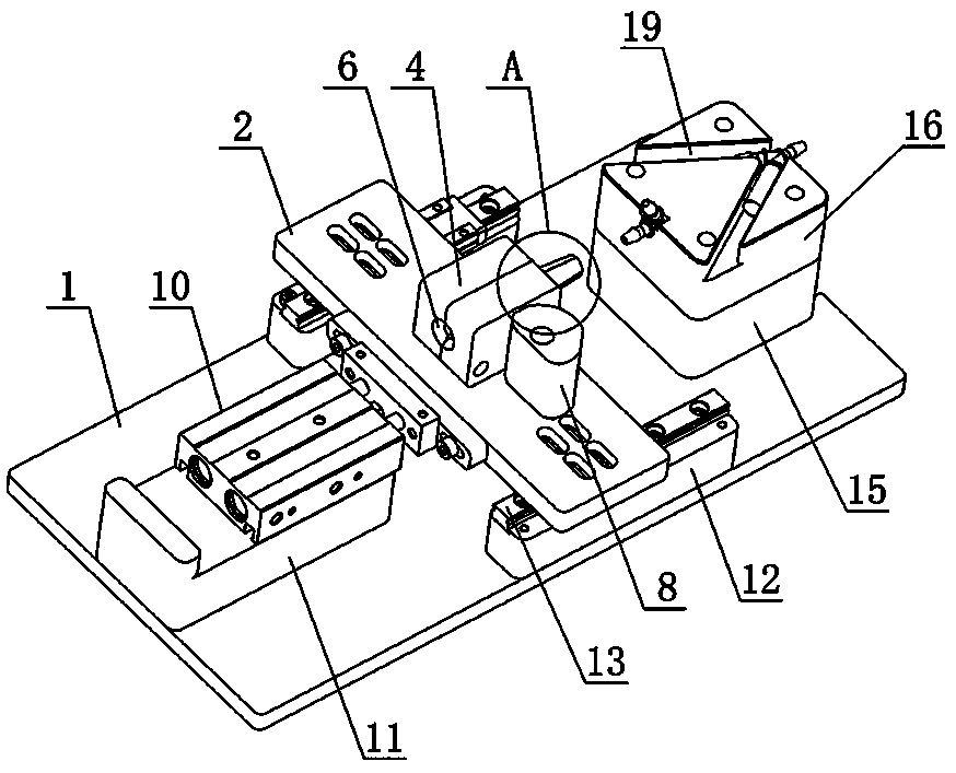
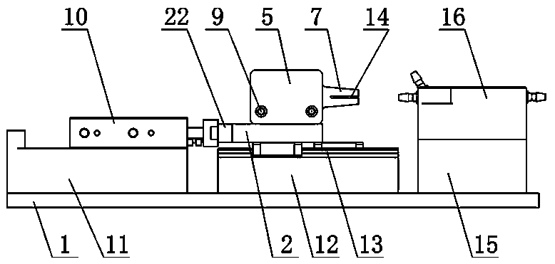
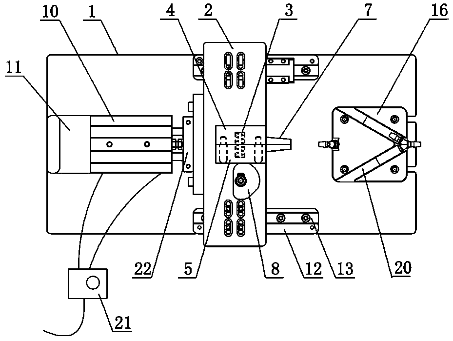
[0023] Such as Figure 1-3 As shown, the automatic intubation machine of the present invention includes a base 1 on which a power source, a clamping assembly and a joint fixing assembly for fixing the connecting pipe are arranged at intervals from left to right, and the power source is a parallel bar cylinder 10 (Of course, other linear drive power sources can also be used, such as hydraulic cylinders, electric push rods, etc.), the double-rod cylinder 10 is fixedly installed on the base 1 through the height block 11; The A port and B port of the valve 21 (4H210-08) are connected, and the P port of the lever valve is connected with the air source. The extension or retraction of the piston rod of the double-rod cylinder 10 is controlled by the lever valve 21 to realize the clamping assembly. Fast back and forth translation left and right;

[0024] Such as Figure 1-3 As shown, the base 1 is provided with a guide assembly, and the guide assembly includes a pair of guide blocks...


PUM


Abstract

The invention discloses an automatic intubating machine. The automatic intubating machine comprises a base, wherein the base is provided with a power source, a clamping assembly and a joint fixing assembly; the power source, the clamping assembly and the joint fixing assembly are arranged at intervals from left to right; the clamping assembly is used for fixing a connecting pipe and comprises a substrate driven by the power source; a fixed clamping block and a movable clamping block which are connected into a whole by an elastic part are arranged on the upper surface of the substrate; a fixedclamping block faying surface and a movable clamping block faying surface are symmetrically provided with arc-shaped grooves; the two arc-shaped grooves define a clamping hole for fixing the connecting pipe; the fixed clamping block and the arc-shaped clamping block are respectively provided with arc-shaped clamping sheets; and an opening and closing wrench is arranged on the front side of the movable clamping block in a laminating manner. The automatic intubating machine disclosed by the invention has the advantages that automatic quick insertion of the connecting pipe and a joint is realized, so that the intubating efficiency is improved; and the automatic intubating machine can meet quick insertion of different joints and different connecting pipes and is wide in application range.

Description

technical field [0001] The invention relates to an intubation machine, in particular to an automatic intubation machine. Background technique [0002] The hydraulic system is an important part of the fully automated in vitro diagnostic equipment and a key factor determining the performance of the in vitro diagnostic equipment. The hydraulic system usually uses joints to connect multiple connecting pipes in series or in parallel to form multiple pipelines. The sealing performance between the joints and the connecting pipes is the prerequisite for ensuring the normal operation of the equipment. [0003] The traditional intubation method is to manually insert the connecting tube and the connector into one body. When the force of both hands exceeds 0.7kg during insertion, the operator will experience hand fatigue. However, when the connector and the connecting tube are inserted, 0.9 kg is required. ~1.9kg of external force, so manual intubation is likely to cause hand fatigue a...

Claims


Application Information

Patent Timeline
IPC IPC(8): B23P19/027B23P19/00
CPCB23P19/027B23P19/00B23P19/001
Inventor 肖凤娟王红凯段军宇屈红旭刘聪余峰许准朱建敏
Owner AUTOBIO LABTEC INSTR CO LTD
Why Eureka
Try Eureka