Marking machine used for road construction

A technology of road construction and marking machine, which is applied in the direction of roads, roads, road repairs, etc., can solve the problems of heavy workload of workers, achieve the effects of reducing labor, improving mixing effect, and preventing sedimentation

Active Publication Date: 2019-10-15
林盛建设集团有限公司
View PDF6 Cites 5 Cited by
  • Summary
  • Abstract
  • Description
  • Claims
  • Application Information

AI Technical Summary

Problems solved by technology

[0003] However, the existing marking machine lacks the function of cleaning the road during the working process. Before the marking operation, the road surface needs to be cleaned manually, and the workload of the workers is heavy.

Method used


Image

  • Marking machine used for road construction
  • Marking machine used for road construction
  • Marking machine used for road construction

Examples


Embodiment 1

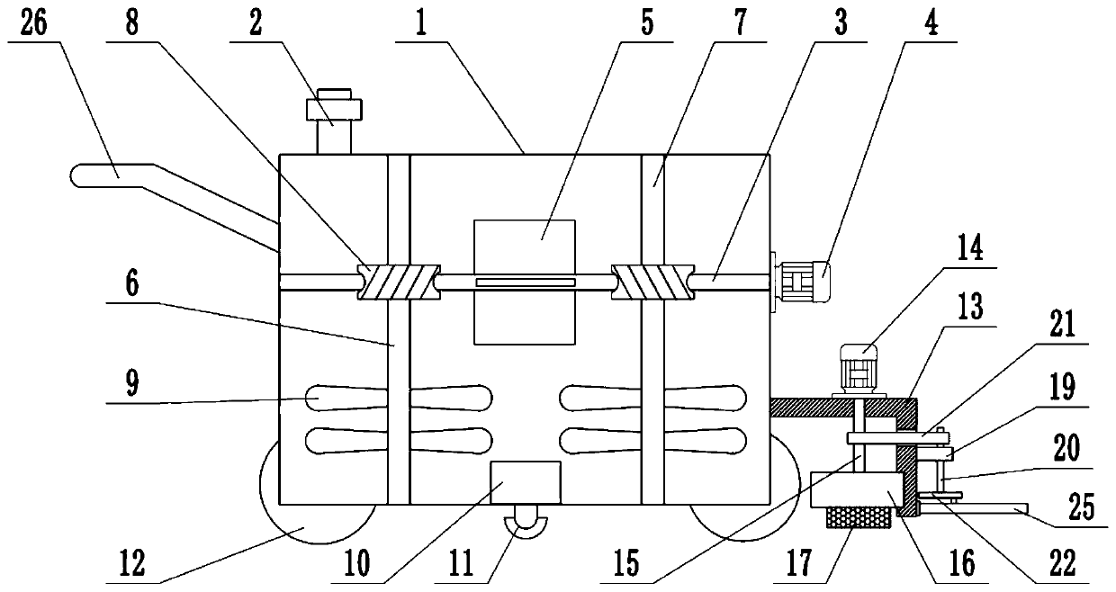
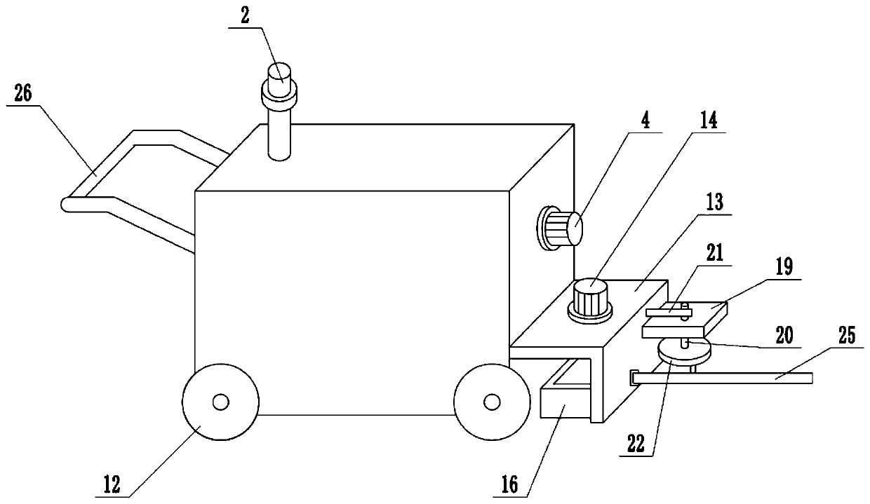
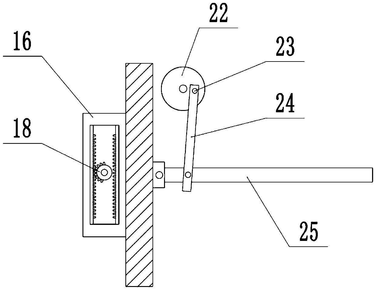
[0021] see Figure 1-3 , in an embodiment of the present invention, a marking machine for road construction, including a box body 1, a booster pump 10 and a nozzle 11, a filling port 2 is installed on the top of the box body 1, and paint is injected through the filling port 2 In the box body 1, a booster pump 10 is installed on the bottom of the box body 1, and a nozzle 11 is installed on the lower surface of the box body 1. The paint in the body 1 is transported to the nozzle 11, sprayed on the ground, and the marking operation is carried out. The bottom of the box body 1 is equipped with rollers 12, which is convenient for the device to move. The upper surface of frame 13 is fixedly connected with cleaning motor 14, and the shaft extension end of cleaning motor 14 is fixedly connected with drive shaft 15, and drive shaft 15 extends to the below of fixed frame 13 through fixed frame 13, and the inside of fixed frame 13 is equipped with gear. Rack frame 16, the rack frame 16 ...

Embodiment 2

[0023] On the basis of Embodiment 1, a stirring mechanism is installed inside the box body 1, and the stirring mechanism includes a worm 3, a stirring motor 4, a stirring plate 5, a left stirring rod 6, a right stirring rod 7, a worm wheel 8 and a stirring blade 9, and the box A worm 3 is installed inside the body 1, the left and right ends of the worm 3 are respectively connected to the side wall of the box 1 in rotation, the outer wall of the box 1 is fixedly connected with a stirring motor 4, and the shaft extension end of the stirring motor 4 is connected to the worm 3 The stirring plate 5 is installed in the middle of the worm 3. When the stirring motor 4 is running, it drives the worm 3 to rotate, and then drives the stirring plate 5 to rotate. The stirring plate 5 is used to stir the paint longitudinally to make the paint evenly mixed. There is a left The stirring rod 6, the right stirring rod 7, the upper and lower ends of the left stirring rod 6 and the right stirring ...


PUM


Abstract

The invention relates to the field of road construction equipment, in particular to a marking machine for road construction. The machine comprises a box body, a booster pump and a nozzle, wherein thebooster pump is arranged at the bottom of the box body, the nozzle is arranged on the lower surface of the box body, a water outlet of the booster pump communicates with the nozzle through a pipeline,a fixing frame is fixedly connected to the side wall of the box body, a sweeping motor is fixedly connected to the upper surface of the fixing frame, a driving shaft is fixedly connected to a shaft extension end of the sweeping motor, a rack frame is arranged in the fixing frame, a sweeping plate is fixedly connected to the lower surface of the rack frame, a semi-gear is arranged at the lower endof the driving shaft in a sleeving mode, and a stirring mechanism is arranged inside the box body. According to the machine, a stirring plate is used for longitudinally stirring paint, a stirring blade is used for transversely stirring the paint, so that the paint is prevented from depositing, in the marking process, the ground is swept by the reciprocating motion of the sweeping plate, the obstacles such as pebbles and plastic bags on the advancing route of the machine are swept by the aid of an obstacle clearing rod, so that the trouble of manual sweeping is saved.

Description

technical field [0001] The invention relates to the field of road construction equipment, more specifically, a marking machine for road construction. Background technique [0002] The marking machine is a road construction machine widely used in roads, high-level roads, parking lots, squares and runways to draw different restrictions, guidelines and warnings on the flat ground. With its fast, efficient, accurate and other advantages, the marking machine has played a huge role in urban planning and road construction, saving the construction period and economic investment of road construction to the greatest extent. The marking machine generally includes an engine, an air compressor, a paint (melt) barrel, a marking bucket (spray gun), a guide rod, a controller, and other devices, and various power-assisted drive carriers are configured as required. [0003] However, the existing marking machine lacks the function of cleaning the road during the working process. Before the ma...

Claims


Application Information

Patent Timeline
IPC IPC(8): E01C23/22
CPCE01C23/22E01C23/225
Inventor 不公告发明人
Owner 林盛建设集团有限公司
Why Eureka
Try Eureka