
Precise and quick positioning method for vision

A positioning method and fast technology, applied in image data processing, measuring devices, instruments, etc., can solve the problems of not being able to make full use of spot image information, and achieve the effects of clear principles, reduced errors, and simple devices

Inactive Publication Date: 2019-10-15
NANJING UNIV OF AERONAUTICS & ASTRONAUTICS
View PDF7 Cites 4 Cited by
  • Summary
  • Abstract
  • Description
  • Claims
  • Application Information

AI Technical Summary

Problems solved by technology

The traditional position detection technology adopted above has obvious deficiencies, and cannot make full use of the spot image information collected by CCD / CMOS to achieve higher precision position detection

Method used


Image

  • Precise and quick positioning method for vision
  • Precise and quick positioning method for vision
  • Precise and quick positioning method for vision

Examples


Embodiment Construction

[0026] Embodiments of the invention are described in detail below, examples of which are illustrated in the accompanying drawings. The embodiments described below by referring to the figures are exemplary only for explaining the present invention and should not be construed as limiting the present invention.

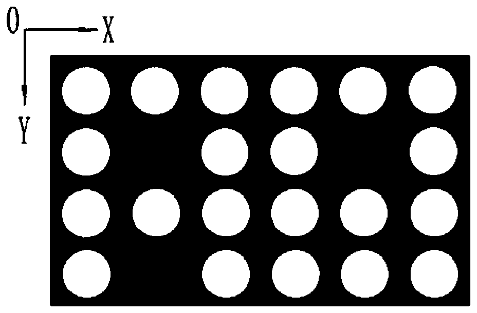
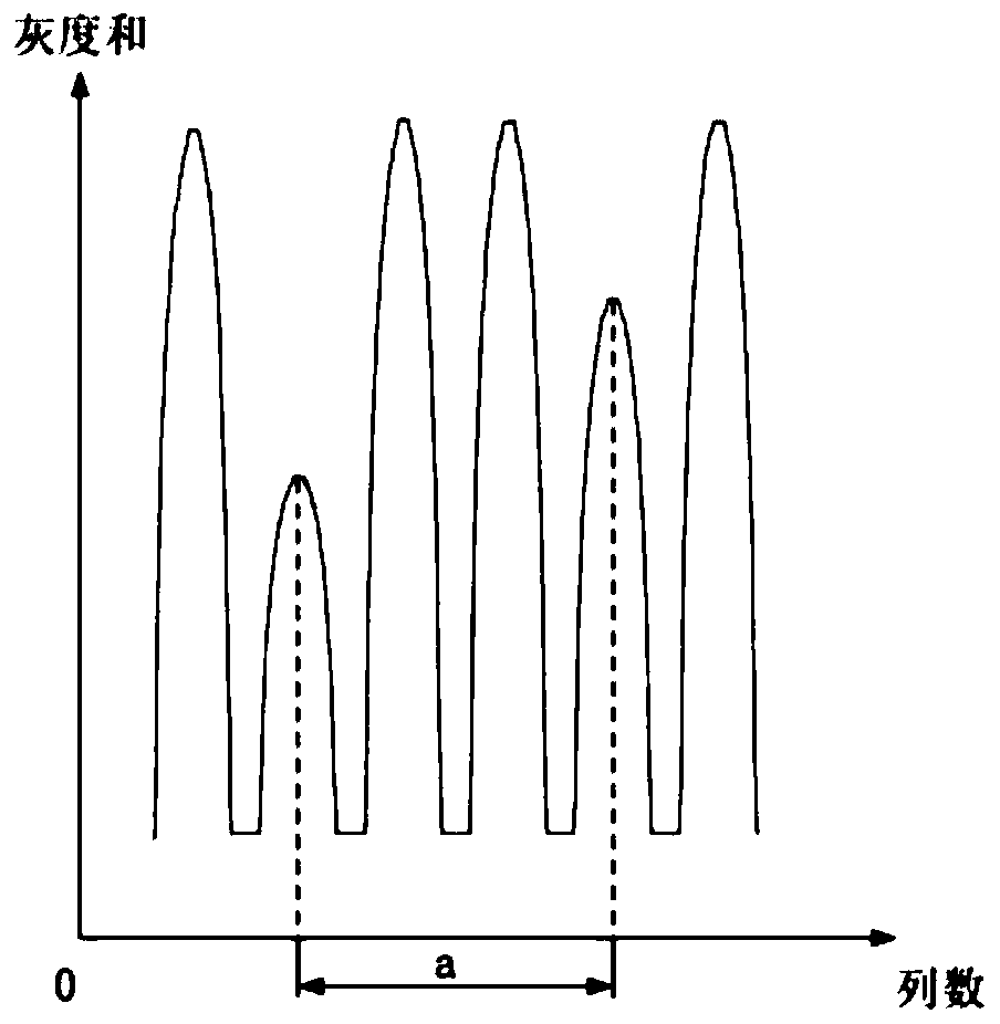
[0027] The design concept adopted in the present invention is: based on the multi-spot imaging method, innovatively adopt machine vision technology to process the relative positions of the light spots at different positions, and use the method of dividing the grid area to extract the precise displacement information of the system, so as to realize non- Contact precision positioning.

[0028] Such as figure 1 As shown, in order to obtain rich spot information, a small hole of the same size is processed on the substrate to make a target, and the backlight is used to illuminate it; the target is attached to the measured object, and when the measured object is displaced , ...


PUM


Abstract

The invention discloses a precise and quick positioning method for vision. On a substrate, small holes with the same size are processed to manufacture a target, a back illumination light source is adopted to carry out illumination on the target; the target is attached to a tested object; when the tested object generates displacement, the target is driven to move, and therefore, all small holes move together; a digital camera is adopted to carry out visual imaging on the target, and the collection of a target light spot and light spot displacement information can be finished through computer image processing; a new sub-region grid positioning method is used for realizing light spot positioning; and therefore, the precise displacement of the tested object is determined. The method innovatively adopts a machine vision technology to process the relative positions of the light spots on different positions, and utilizes a grid region division way to extract the precise displacement information of the system so as to realize non-contact precise positioning, errors can be effectively reduced, and light spot micrometric displacement accuracy is improved.

Description

technical field [0001] The invention relates to a visual precise and rapid positioning method, which belongs to the technical field of non-contact high-precision two-dimensional micro-displacement measurement. Background technique [0002] With the continuous advancement of computer technology and image processing methods, machine vision technology has been greatly developed, and machine vision technology based on CCD or CMOS has been widely used in geometric measurement. Generally speaking, in the positioning measurement system based on machine vision, the traditional scanning method of the computer system is to recognize the target features one by one and point by point, and locate the center of the individual light spots acquired by the camera until the light spots that need to be collected are recognized. The method is time-consuming and cumbersome, and the obtained light spot positions are few, the utilization rate of CCD / CMOS is low, and the improvement of positioning ...

Claims


Application Information

Patent Timeline
Patent Type & Authority Applications(China)
IPC IPC(8): G01B11/00G01B11/02G06T7/70
CPCG01B11/00G01B11/02G06T7/70G06T2207/30208
Inventor 杨德华成颖吴常铖费飞
Owner NANJING UNIV OF AERONAUTICS & ASTRONAUTICS
Features
  • Generate Ideas
  • Intellectual Property
  • Life Sciences
  • Materials
  • Tech Scout
  • Unparalleled Data Quality
  • Higher Quality Content
  • 60% Fewer Hallucinations
Learn More