Supercharge Your Innovation With Domain-Expert AI Agents!

linear motor

A technology for linear motors and machines, applied in circuits, magnetic objects, mechanical equipment, etc., to solve problems such as bulkiness, increase in overall equipment cost and size, and damage to the integrity of input functions

Active Publication Date: 2021-10-29
LIBERTINE FPE
View PDF9 Cites 0 Cited by
  • Summary
  • Abstract
  • Description
  • Claims
  • Application Information

AI Technical Summary

Problems solved by technology

[0008] Second, servohydraulic systems require expensive and specialized infrastructure within the test facility, which can be extremely bulky, and must still be located relatively close to the hydraulic actuators to limit the inertia of the oil moving within the system
Additionally, the infrastructure requires professional expertise to operate and maintain
[0009] Third, servohydraulic systems are large consumers of electricity, making their operation expensive and contributing to the carbon footprint of vehicle development and manufacturing
[0010] Fourth, servohydraulic systems can be extremely noisy, making it difficult to distinguish between noise due to the test object's response and the associated noise of the test actuator system itself
This extra inertia reduces the peak frequency the actuator can achieve for a given displacement
[0016] Second, the use of compliant members such as airbags or mechanical springs introduces the potential for unwanted resonances in the test actuator system, compromising the integrity of the input function applied to the test object
[0017] Third, due to the need to couple discrete spring and motor assemblies within each actuator test frame, the arrangement taught by US7401520 requires unnecessary structural complexity, resulting in increased cost and size of the overall apparatus
This friction will affect the net force applied to the test object and may also cause wear and shortened life of the actuator
[0022] Third, the arrangement taught by US8844345 requires unnecessary structural complexity due to the need to couple motors, pneumatic cylinders, movable members and mounts for test objects within each actuator test frame, resulting in overall equipment cost and size increase
The linear motors typically used in free piston engines are rarely able to achieve the desired level of motion control due to the high piston mass of these machines relative to the force that can be exerted by the motor

Method used


Image

  • linear motor
  • linear motor
  • linear motor

Examples


Embodiment Construction

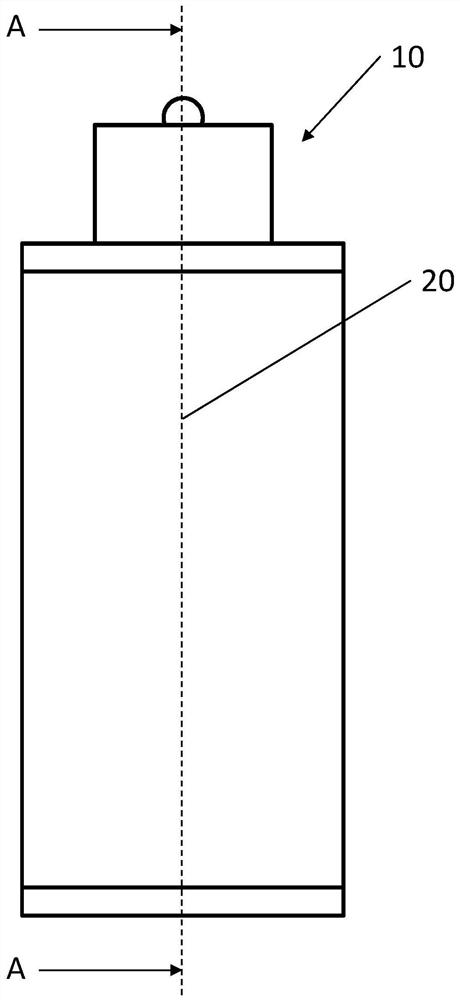
[0065] figure 1 is an external view of a first LEM operating as an actuator 10 with an axis of motion 20 along which a translating body (shown later) moves along the axis of motion 20 and the various planar positions for the other cross-sectional views.

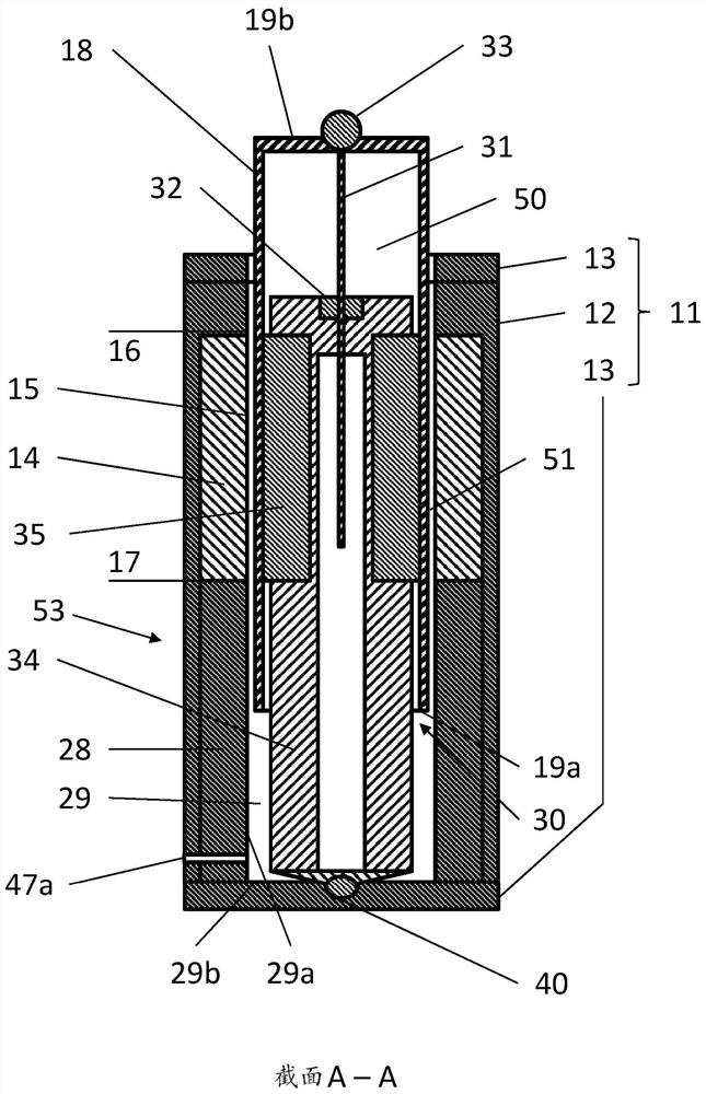
[0066] figure 2 The actuator 10 is shown with a housing body 11 . The housing body 11 is formed by a typically cylindrical wall 12 and by end walls 13 so as to define a hollow interior. Inside holds a stator 14 which is typically a tubular linear motor stator having a cylindrical bore 15 extending axially from one end 16 to the other 17 of the stator. Thus, the housing body and the stator define the working cylinder 53 . The central core 34 is fixed at least axially within the working cylinder relative to the stator 14 and in this arrangement the central core 34 is fixed to the end wall 13 at a central core fixing point 40 . The upper end of the central core 34 is surrounded by the hollow translating body 18 such that th...


PUM


Abstract

A linear motor (LEM) comprising: a stator mounted in a housing, the housing and stator defining a working cylinder; a central core within the working cylinder defining a cylindrical stator bore between the central core and the working cylinder; a hollow translating body , can move axially in the working cylinder, extend into the stator bore and form an external magnetic circuit air gap between the translation body and the stator; at least one fluid bearing provides a bearing gap between the central core and the translation body, where the center The core is fixed axially with respect to the stator, wherein the at least one fluid bearing provides coaxial positioning of the translating body and the central core.

Description

technical field [0001] The invention relates to a linear motor. Background technique [0002] Such linear motors can be used in a variety of applications including, but not limited to: use as a free piston engine linear generator, where combustion pressure acts on a translating body to produce useful electrical output; as a gas expander, where high pressure gas acts on On a translator to produce a useful electrical output; as a gas compressor, where the electrical input causes movement of the translator to pressurize the gas; in hydraulic systems, where movement of the translator causes displacement of hydraulic fluid within the working chamber , or displacement of hydraulic fluid within a working chamber to cause movement of a translating body; and as an actuator, where an electrical input causes movement of a translating body to produce a desired actuation effect. [0003] Such actuators can be used in displacement and vibration testing systems, manufacturing processes, a...

Claims


Application Information

Patent Timeline
Patent Type & Authority Patents(China)
IPC IPC(8): G01M7/00G01M17/00G01M7/02G01M17/007G01M17/04
CPCG01M7/02G01M17/007G01M17/04H02K5/203H02K41/031H02K41/03H02K11/21H02K41/033H02K5/167F16C32/06H01F7/1607H02K5/165H02K7/088H02K7/14H02K7/1876H02K41/02H02K33/00H02K35/00F02B71/04H02K7/08H02K7/1884H02K33/18
Inventor 爱德华·海恩斯塞缪尔·科克里尔
Owner LIBERTINE FPE
Features
  • R&D
  • Intellectual Property
  • Life Sciences
  • Materials
  • Tech Scout
  • Unparalleled Data Quality
  • Higher Quality Content
  • 60% Fewer Hallucinations
Learn More