
Anti-blocking structure of sodium hypophosphite reaction kettle buffer tank

A sodium hypophosphite and buffer tank technology, applied in the field of chemical production, can solve problems such as increased safety hazards, material running, and lime scaling accumulation, and achieve the effects of ensuring safety, preventing material running, and effective separation

Inactive Publication Date: 2019-10-18
江苏和纯化学工业有限公司
View PDF12 Cites 0 Cited by
  • Summary
  • Abstract
  • Description
  • Claims
  • Application Information

AI Technical Summary

Problems solved by technology

[0004] The patent application number is CN201120285626.3. The technical scheme of the utility model patent "An anti-flush buffer tank for the synthesis reaction of sodium hypophosphite" mentions that a buffer tank is equipped above the reaction kettle. According to the summary of the company's many years of production experience, Practice has proved that the above buffer tank with oval bottom has a good effect in the initial stage of use, but with the passage of time, a large amount of lime scale will accumulate at the oval head of the buffer tank, and eventually the lower return pipe will be blocked, and the reaction liquid in the buffer tank will It is impossible to flow back into the kettle, which will eventually cause the reactor feed liquid to escape from the top emptying pipe; once the backflow pipe is seriously blocked, the gas discharge speed will not be fast during violent reactions, and the pressure inside the kettle will increase, increasing safety hazards in the production process

Method used


Image

  • Anti-blocking structure of sodium hypophosphite reaction kettle buffer tank

Examples


Embodiment Construction

[0011] The technical solution of the present invention will be further described below according to the accompanying drawings.

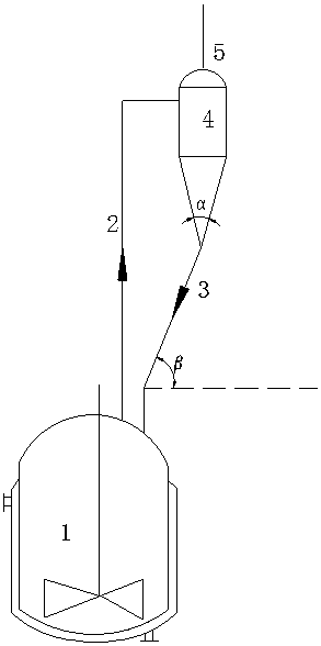
[0012] Such as figure 1 The anti-clogging structure of the buffer tank of the sodium hypophosphite reactor shown in the structure includes a reactor 1, an outlet pipe 2, a return pipe 3, a buffer tank 4, and an outlet pipe 5 of the buffer tank; wherein the buffer tank 4 is located above the reactor 1 , the bottom of the buffer tank 4 is connected to the top return inlet of the reactor 1 through a return pipe, the gas outlet at the top of the reactor 1 is connected to the side top of the buffer tank 4 through the gas outlet pipe 2, and the buffer tank gas outlet pipe 5 is arranged on the top of the buffer tank 4 surface.

[0013] The bottom of the buffer tank 4 is a cone bottom, and the optimum cone angle α is 25 to 35°;

[0014] The air outlet pipe 2 enters in the upper part of the cylinder of the buffer tank 4 along the tangential direction, and t...


PUM


Abstract

The invention discloses an anti-blocking structure of a sodium hypophosphite reactor kettle buffer tank, which comprises a reaction kettle, an air outlet pipe, a return pipe, a buffer tank, and a buffer tank air outlet pipe. The buffer tank is arranged above the reaction kettle, the bottom of the buffer tank is connected with the reflux inlet at the top of the reaction kettle through the return pipe, an air outlet in the top of the reaction kettle is connected to the top of the side surface of the buffer tank through the air outlet pipe, and the buffer tank air outlet pipe is arranged on the upper surface of the top of the buffer tank; the bottom of the buffer tank is a cone bottom, the angle of cone alpha is 25 to 35 degrees, and the tilt angle beta of the return pipe with respect to thehorizontal direction is greater than 45 degrees; and the air outlet pipe enters from the upper part of a barrel body of the buffer tank in the direction of the tangent line, and the tangent line is atthe position of about two-thirds to four-fifths of the height of the barrel body of the buffer tank from bottom to top. The anti-blocking structure of the sodium hypophosphite reactor kettle buffer tank has the advantages that it is ensured that gas entrained liquid produced through sodium hypophosphite reaction is effectively separated in the buffer tank, the buffer tank is not blocked after being used, the phenomenon of material running is prevented, and it is ensured that the production process is safely carried out.

Description

technical field [0001] The invention provides an anti-clogging structure of a buffer tank of a sodium hypophosphite reaction kettle, which belongs to the technical field of chemical production. Background technique [0002] Sodium hypophosphite is a strong reducing agent widely used in modern industrial production process. It can explode when in contact with oxidizing agents. It is mainly used in chemical plating, surface metallization of non-metallic materials, water treatment agents, antioxidants and other fields. The main raw materials for the production of sodium hypophosphite are yellow phosphorus, liquid caustic soda, and calcium oxide, which are synthesized in a reactor. The reaction liquid is filtered, impurity removed, hypophosphorous acid is adjusted to pH, concentrated, crystallized, and packaged to obtain sodium hypophosphite. Crystal finished. [0003] A large amount of phosphine gas is produced during the reaction of sodium hypophosphite. As the reaction progr...

Claims


Application Information

Patent Timeline
Patent Type & Authority Applications(China)
IPC IPC(8): B01J19/18C01B25/165
CPCB01J19/18C01B25/165
Inventor 冯振华朱雪松刘仕通刘平高宏福
Owner 江苏和纯化学工业有限公司
Learn More