
Compression molding method of thermoplastic composite component with I-shaped reinforcing ribs

A composite material component and compression molding technology, which is applied in the field of compression molding of thermoplastic composite components, can solve the problems of high molding cost, high price, and complicated molding process, and achieve simplified equipment and technology, convenient and fast processing, and high dimensional accuracy Effect

Active Publication Date: 2019-10-18
CENT SOUTH UNIV
View PDF7 Cites 5 Cited by
  • Summary
  • Abstract
  • Description
  • Claims
  • Application Information

AI Technical Summary

Problems solved by technology

In the autoclave, the pressure of the filled gas is used to form a uniform pressure on the composite material, so the molding of the I-shaped stringer of the composite material can be easily realized in the autoclave, but the equipment of the autoclave is expensive, and the molding cost is high, and The molding process is more complicated, time-consuming and labor-intensive, and it is difficult to meet the requirements of industrialization

Method used


Image

  • Compression molding method of thermoplastic composite component with I-shaped reinforcing ribs
  • Compression molding method of thermoplastic composite component with I-shaped reinforcing ribs
  • Compression molding method of thermoplastic composite component with I-shaped reinforcing ribs

Examples


Embodiment Construction

[0038] The embodiments of the present invention will be described in detail below with reference to the accompanying drawings, but the present invention can be implemented in various ways defined and covered by the claims.

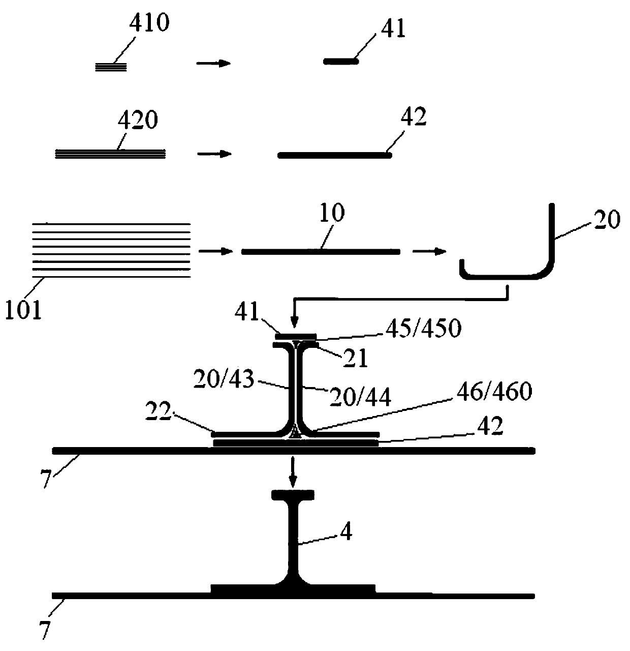
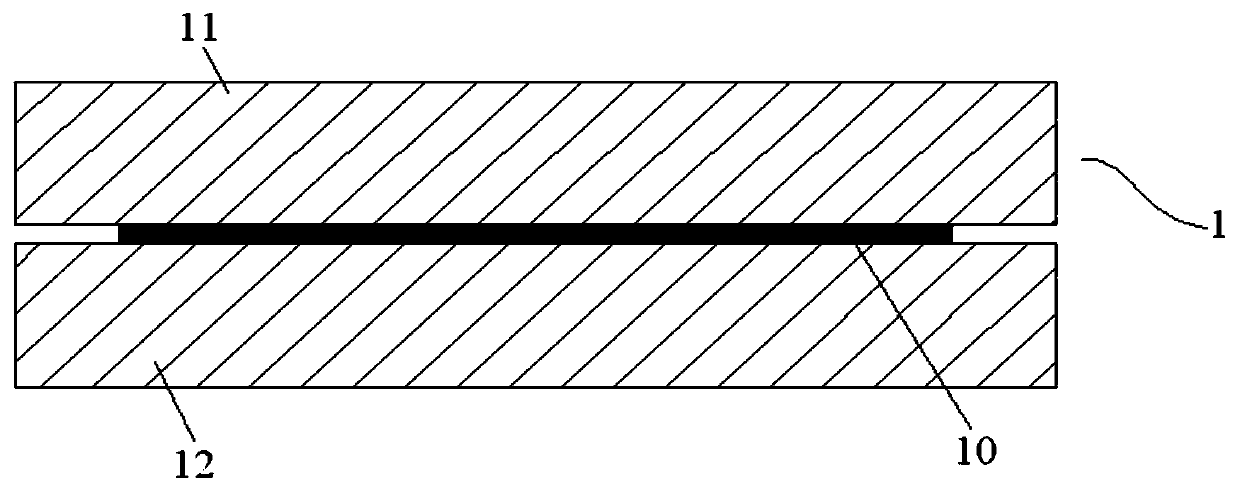
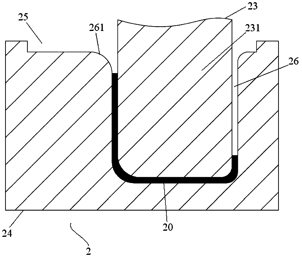
[0039] see figure 1 The compression molding method steps of the I-shaped reinforced member of the preferred embodiment of the present invention, and Figure 2 to Figure 6 The molding method of the I-shaped reinforced member in the preferred embodiment of the present invention is provided with a selected mold.

[0040] In this embodiment, the material of the upper edge block, the lower edge block, the upper filling block, the lower filling block, the I-shaped reinforcing rib and the main body wall board is a thermoplastic resin-based composite material such as carbon fiber reinforced polyether ether ketone.

[0041] see figure 1 , the molding method of the I-shaped reinforced member of the present embodiment comprises the following steps:

[0042] S1) Ma...


PUM


Abstract

The invention provides a compression molding method of a thermoplastic composite component with I-shaped reinforcing ribs. The compression molding method of the thermoplastic composite component withthe I-shaped reinforcing ribs includes: first prefabricating a flat plate prefabricated member and upper and lower edge block prefabricated members from thermoplastic composite prepreg sheets throughprimary mold pressing, then prefabricating two C-shaped prefabricated members by performing secondary mold pressing on the flat plate prefabricated member, then performing preassembly on the I-shapedreinforcing ribs by using the upper and lower edge block prefabricated members in combination, and finally preforming third mold pressing for shaping the component. Wide-end-up inclined planes are arranged on a left trapezoid strip and a right trapezoid strip of an I-shaped reinforcing rib component mold, and downward mold pressure of a pressing block is converted by the left trapezoid strip and the right trapezoid strip into horizontal direction pressure pointing at the I-shaped reinforcing ribs. The compression molding method of the thermoplastic composite component with the I-shaped reinforcing ribs overcomes the problems that multidirectional pressure transmission cannot be performed and a complex component is difficult in molding pressure transmission, and therefore the complex component is uneven in thickness, high in porosity rate and the like, thereby achieving low cost manufacture of the I-shaped reinforcing rib component, and laying a foundation for application of advanced thermoplastic resin matrix composites in the aviation field.

Description

technical field [0001] The invention relates to the technical field of composite material forming, in particular to a compression molding method of a thermoplastic composite material component with an I-shaped reinforcing rib. Background technique [0002] Thermoplastic resin-based composite materials (referred to as thermoplastic composite materials in this application) have good heat resistance, excellent damage tolerance, good impact resistance, short molding cycle, high production efficiency, and repeated molding. The aerospace field is gaining more and more attention. A class of advanced thermoplastic composite materials represented by carbon fiber reinforced polyether ether ketone is increasingly applied to the main / secondary load-bearing components in the aviation field. Poor performance and penetrability, difficulty in bonding between adjacent layers, difficulty in eliminating voids in the laminate, and difficulty in resin flow during the molding process, so the man...

Claims


Application Information

Patent Timeline
Patent Type & Authority Applications(China)
IPC IPC(8): B29C70/44B29K101/12
CPCB29C70/446B29K2101/12
Inventor 湛利华戴光明关成龙黄明辉赵国庆
Owner CENT SOUTH UNIV
Learn More