
Substitute bogie assembly and alighting method

A bogie and assembly technology, which is applied in the field of rail vehicles, can solve the problems of being unsuitable for mass production, less off-board processes, and difficult to apply to the assembly of low-floor trams, etc., and achieves simple structure, small size, and low production costs. Effect

Active Publication Date: 2019-10-18
CRRC DALIAN CO LTD
View PDF6 Cites 2 Cited by
  • Summary
  • Abstract
  • Description
  • Claims
  • Application Information

AI Technical Summary

Problems solved by technology

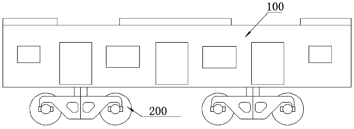
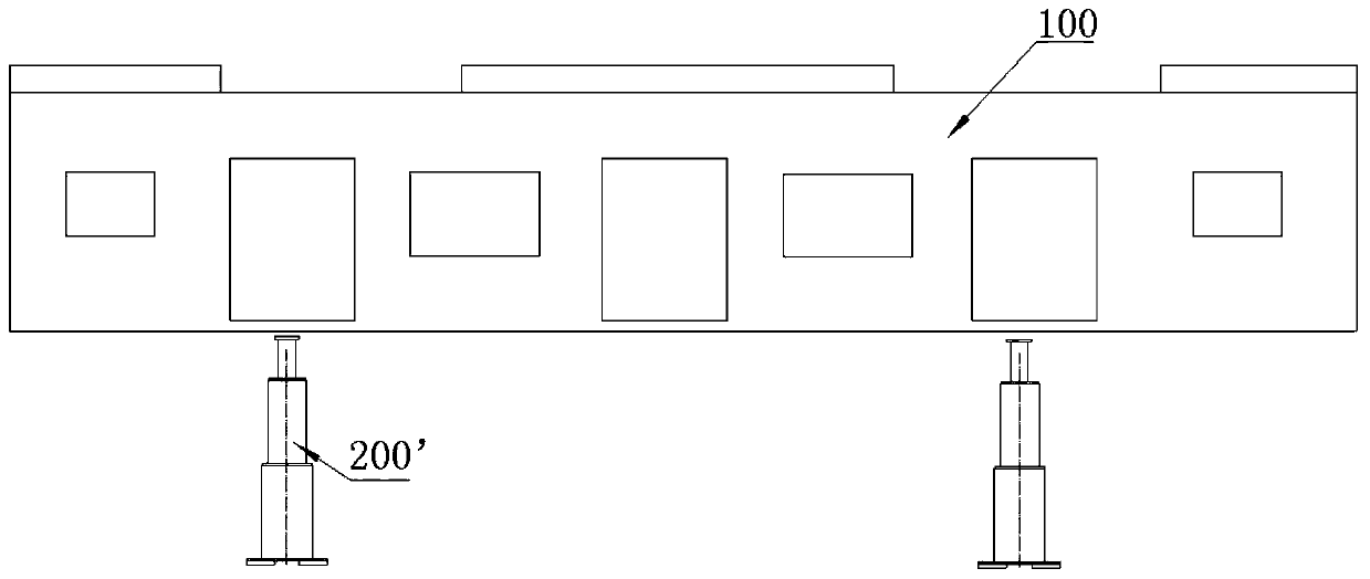
Therefore, the fixture 200' is difficult to apply to the final assembly of low-floor trams
[0005] It can be seen that, due to the small size of the car body of the low-floor tram and fewer steps under the car, the substitute bogie used in the original assembly production mode is not suitable for the mass production of this type of vehicle

Method used


Image

  • Substitute bogie assembly and alighting method
  • Substitute bogie assembly and alighting method
  • Substitute bogie assembly and alighting method

Examples


Embodiment 1

[0063] Such as Figure 10 As shown, core shafts 210 are distributed symmetrically at the four corners of the bottom of the car body 100 in the middle compartment. When getting off the car, only the first-generation bogie 310 is selected, and the four cylindrical mandrels 210 of the car body 100 are respectively inserted into the fixed disks 3122 of the fixing devices 312 at the four corners of the first-generation bogie 310. In the hole, the car can be dropped off.

Embodiment 2

[0065] Such as Figure 11 As shown, the bottom of the vehicle body 100 of the leading vehicle has four spindles 210 distributed asymmetrically. When getting off the car, the bogie 310 for the first generation and the bogie 320 for the second generation can be used in combination. First, the pin shaft is inserted into the first connection device 314 of the first substitute bogie 310 and the second connection device 324 of the second substitute bogie 320 to make it combined into a whole; secondly, the four cylindrical cores of the car body 100 The shafts are respectively inserted into the fixed disks 3122 of the fixing devices 312 at the four corners of the first substitute bogie 310; The lower surface of 100 can be finished getting off the car.

Embodiment 3

[0067] Such as Figure 12 As shown, the bottom of the car body 100 of the middle compartment is not arranged with a mandrel. When getting off the car, select a pair of bogies 330 for the third generation to fix the two ends of the car body 100 respectively. First, the position of the four corners of the end of the car body 100 is installed with a positioning tool 231 that includes a positioning pin; secondly, insert the positioning pin of the positioning tool 231 into the round hole of the fixing seat 334 of the third substitute bogie 330 to Position the car body 100, and unscrew the threaded support 3222 to fit it to the lower surface of the car body 100 to support the car body 100; and finally, disassemble the positioning tooling 231 at both ends of the car body to complete the landing.

[0068] It should be understood that the third-generation bogie 330 is not only applicable to the vehicle body 100 without a mandrel arranged at the bottom, but also applicable to a car bod...


PUM


Abstract

The invention discloses a substitute bogie assembly. The substitute bogie assembly comprises a first substitute bogie; and the first substitute bogie comprises a first framework, a plurality of fixingdevices arranged on the first framework and a plurality of wheels, wherein the positions of the fixing devices correspond to the positions of core shafts at the bottom of a vehicle body, and the wheels are mounted on the first framework through bearings. The substitute bogie assembly is completely matched with a bottom frame structure of a low-floor tramcar, and the substitute bogie assembly is simple in structure and convenient to use. The invention further provides an alighting method using the substitute bogie assembly.

Description

technical field [0001] The invention relates to the field of rail vehicles, in particular to a low-floor tramcar assembly and a substitute bogie assembly for connected trains and a car alighting method using the substitute bogie assembly. Background technique [0002] Compared with traditional rail vehicles, low-floor trams have the advantages of flexibility, convenience, strong adaptability and low operating costs, making them gradually become an important part of urban transportation. The substitute bogie is used as a carrier for transshipment and temporary storage of the car body, and has become an indispensable mechanical component in the process of rail vehicle assembly and train connection. Most of the substitute bogies commonly used in the prior art are suitable for traditional subway urban rail vehicles, and generally include the following two forms: [0003] (1) if figure 1 Shown is an existing substitute bogie 200, which uses a center pin hole to connect with the...

Claims


Application Information

Patent Timeline
Patent Type & Authority Applications(China)
IPC IPC(8): B61F5/02B61F5/18B61F5/52
CPCB61F5/02B61F5/18B61F5/52
Inventor 李仲杨何玲林诗涵陈琛唐世周卜庆富
Owner CRRC DALIAN CO LTD
Learn More