
A petroleum gas ignition device

An ignition device, petroleum gas technology, applied in combustion ignition, ignition by electric spark, gas fuel burner, etc., can solve problems such as environmental pollution, methane poisoning, and greenhouse effect

Active Publication Date: 2020-12-25
UNIV OF SCI & TECH OF CHINA
View PDF5 Cites 0 Cited by
  • Summary
  • Abstract
  • Description
  • Claims
  • Application Information

AI Technical Summary

Problems solved by technology

LPG is usually separated by oil-gas separation device and discharged to the atmosphere through oil pipes, and ignited at the end. However, due to the unstable flow rate of LPG or strong external wind, it is easy to cause LPG to burn and extinguish, which may lead to these unidentified The burning petroleum gas is directly discharged into the atmosphere, polluting the environment and producing a greenhouse effect, and causing vapor cloud explosions, methane poisoning and other hazards, which seriously threaten the safety of on-site personnel

Method used


Image

  • A petroleum gas ignition device
  • A petroleum gas ignition device
  • A petroleum gas ignition device

Examples


Embodiment Construction

[0023] The core of the present invention is to provide a petroleum gas igniter. The structural design of the petroleum gas igniter can ensure the continuous and stable combustion of petroleum gas under the condition of gas discharge, and ensure the safety of oil field equipment and personnel.

[0024] The following will clearly and completely describe the technical solutions in the embodiments of the present invention with reference to the accompanying drawings in the embodiments of the present invention. Obviously, the described embodiments are only some, not all, embodiments of the present invention. Based on the embodiments of the present invention, all other embodiments obtained by persons of ordinary skill in the art without making creative efforts belong to the protection scope of the present invention.

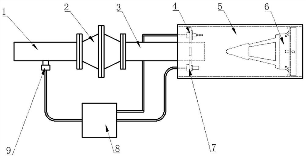
[0025] see figure 1 , figure 1 Schematic diagram of the structure of the petroleum gas ignition device provided by the embodiment of the present invention.

[0026] A...


PUM


Abstract

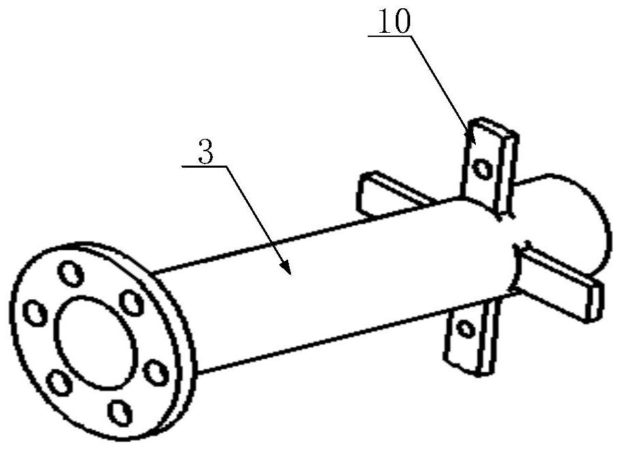
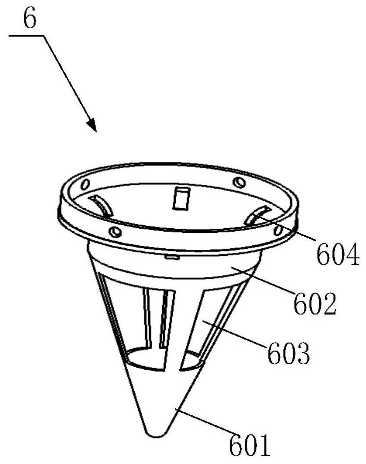
The invention discloses a petroleum gas ignition device which comprises a pipeline, a windproof torch, an ignition box, a gas sensor, a thermocouple and an ignition gun. One end of the pipeline is arranged in the windproof torch. The gas sensor is arranged in the pipeline. The thermocouple and the ignition gun are located in the windproof torch. The gas sensor and the thermocouple are connected with the signal input end of the ignition box. The ignition gun is connected with the signal output end of the ignition box. The ignition box has gas flowing in the pipeline, and when the temperature inthe windproof torch is lower than the preset value, the ignition gun is controlled to achieve ignition. If not gas flows in the pipeline or gas flows in the pipeline but the temperature in the windproof torch is high, the ignition box only controls the gas sensor and the thermocouple to continue detection, and no ignition instruction is sent out. According to the petroleum gas ignition device, the ignition gun can be controlled for ignition in time to consume gas in the pipeline, it is ensured that petroleum gas is combusted continuously and stably, meanwhile, un-combusted petroleum gas is prevented from being discharged into the atmosphere, and safety of oil field equipment and personnel is guaranteed.

Description

technical field [0001] The invention relates to the technical field of oil exploitation equipment, in particular to a petroleum gas ignition device. Background technique [0002] During the well test and production stage of the oil field, a certain amount of petroleum gas is discharged, and its main components are methane, ethane and other gases. Due to the small output, the high cost of collection and transportation, and no economic value, the method of in-situ combustion is adopted to reduce the pollution to the atmospheric environment. LPG is usually separated by oil-gas separation device and discharged to the atmosphere through oil pipes, and ignited at the end. However, due to the unstable flow rate of LPG or strong external wind, it is easy to cause LPG to burn and extinguish, which may lead to these unidentified The burned petroleum gas is directly discharged into the atmosphere, polluting the environment and producing the greenhouse effect, and producing vapor cloud...

Claims


Application Information

Patent Timeline
IPC IPC(8): F23Q3/00F23Q21/00F23D14/26
CPCF23D14/26F23Q3/00F23Q21/00
Inventor 咸玉席卢德唐
Owner UNIV OF SCI & TECH OF CHINA
Learn More