Electric test device
An electrical test and current test technology, applied in the direction of measuring device, measuring device casing, measuring electricity, etc., can solve the problems of delayed test cycle, complicated measurement work, low efficiency, etc., to increase friction and improve stability. Effect
- Summary
- Abstract
- Description
- Claims
- Application Information
AI Technical Summary
Problems solved by technology
Method used
Image
Examples
Embodiment 1
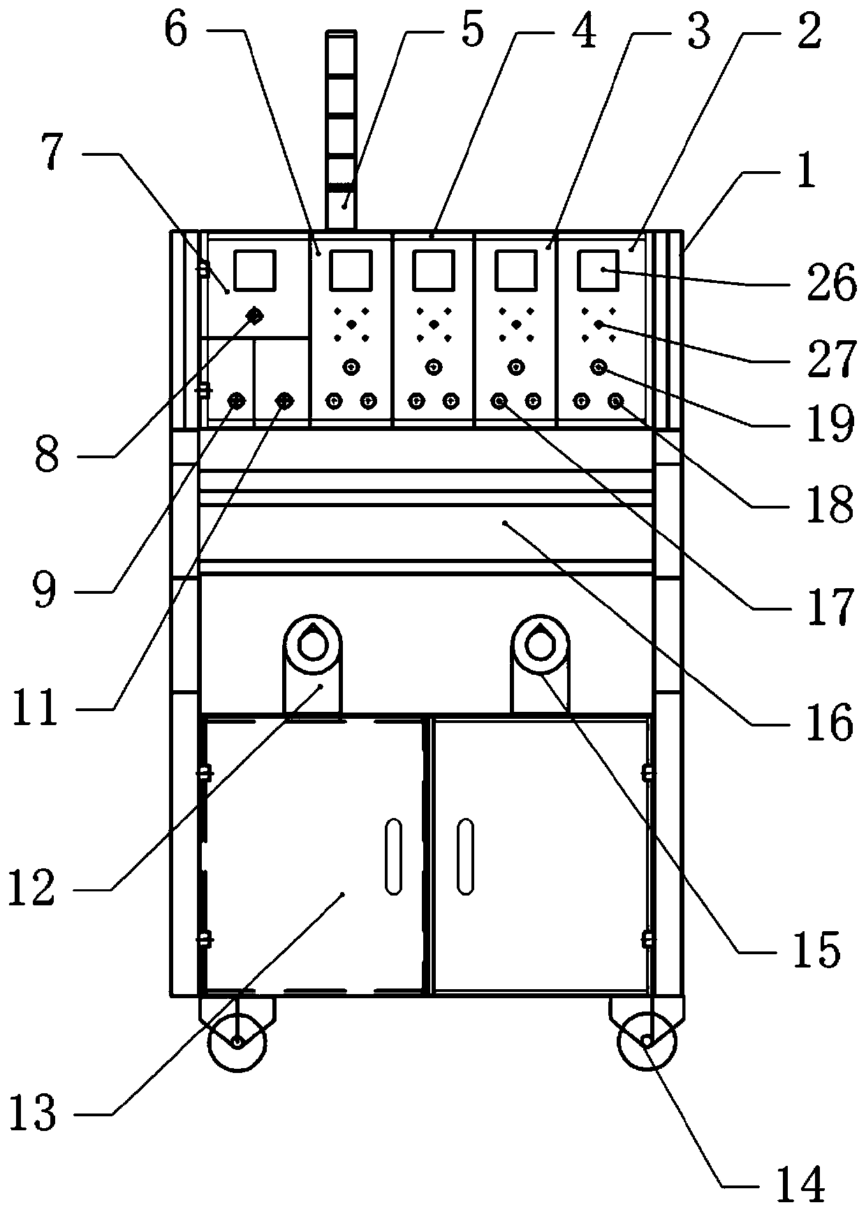
[0041] An electrical test device, such as the attached figure 1 And attached figure 2 As shown, including the test box 1 and the input table 7 fixed on the test box 1, the low-voltage test table I6, the DC test table 4, the low-voltage test table II3 and the current test table 2. The input meter 7 is electrically connected to a power supply, the input meter 7 is electrically connected to a current regulator 12 and a voltage regulator 15, the current regulator 12 regulates the current of the circuit, the model of the current regulator 12 is: BC1, and the voltage regulator 15 regulates the voltage The size of the voltage regulator 15 is: us-52.
[0042] The input meter 7 is electrically connected with a display lamp 8, an emergency stop switch 9 and an alarm switch 11, and the current of the input meter 7 can be disconnected by the emergency stop switch 9, thereby allowing the input meter 7 to stop working. The alarm switch 11 includes a buzzer and a button switch whose model...
Embodiment 2
[0050] The difference between embodiment two and embodiment one is that, as attached figure 1 As shown, the top of the test box 1 is provided with a wiring rack 5 to organize and fix the circuit wires. The upper part of the test box 1 is provided with a working platform 16, and the working platform 16 is used for placing corresponding detection tools. The bottom of the test box 1 is rotatably connected with universal wheels 14, through which the movement of the test box 1 is facilitated.
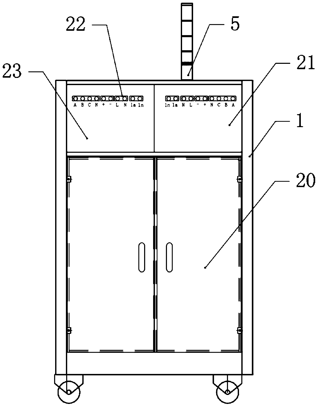
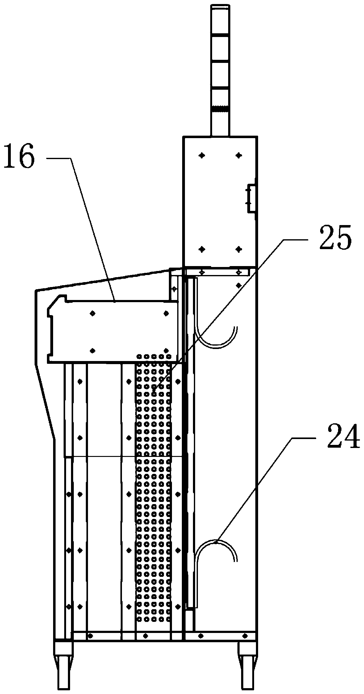
[0051] The bottom of the working platform 16 is provided with a dust removal chamber 13 and a door panel for closing the dust removal chamber 13, such as figure 2 As shown, the back of the test box 1 is provided with a wire storage box 20 and a door panel for closing the wire storage box 20 . attached image 3 As shown, heat dissipation holes 25 are arranged on both sides of the test box 1, and a wire hanger 24 is fixed in the wire storage box 20 by fastening bolts.
[0052] as attached...
Embodiment 3
[0055] The difference between embodiment three and embodiment two is that, as attached Figure 6 And attached Figure 7 As shown, the dust removal chamber 13 is fixedly connected with the dust removal box 32 by fastening bolts, and the wire storage box 20 is rotatably connected with the wire wheel 31, and the left side of the wire wheel 31 is fixed with a rotating shaft 34, and the left end of the rotating shaft 34 extends through the test chamber 1 to In the dust box 32. The right side of the rotating shaft 34 is a smooth surface, and the left side of the rotating shaft 34 is a threaded surface. The left side of rotating shaft 34 is threadedly connected with the slide plate 33 that is positioned at dust removal box 32, and both sides up and down of slide plate 33 are all provided with projection, and the sidewall of dust removal box 32 is provided with the sliding groove that is horizontally slidably connected with projection. A number of evenly distributed fixing holes are...
PUM
 Abstract
Description
Claims
Application Information
 - R&D
- Intellectual Property
- Life Sciences
- Materials
- Tech Scout
- Unparalleled Data Quality
- Higher Quality Content
- 60% Fewer Hallucinations
Browse by: Latest US Patents, China's latest patents, Technical Efficacy Thesaurus, Application Domain, Technology Topic, Popular Technical Reports.
© 2025 PatSnap. All rights reserved.Legal|Privacy policy|Modern Slavery Act Transparency Statement|Sitemap|About US| Contact US: help@patsnap.com


