
Amplitude limiting circuit

A limiter circuit and circuit technology, applied in the direction of electrical components, transmission systems, pulse shaping, etc., can solve the problems of limited isolation of circulators, receiver low-noise amplifier burnout, receiver damage, etc., to achieve excellent ESD performance, insertion The effect of small loss and large bandwidth

Pending Publication Date: 2019-10-18
上海安其威微电子科技有限公司
View PDF0 Cites 0 Cited by
  • Summary
  • Abstract
  • Description
  • Claims
  • Application Information

AI Technical Summary

Problems solved by technology

Therefore, there are mainly two situations that will cause damage to the receiver. One situation is that the interference signal with large external power is directly received by the antenna and enters the receiver. If there is no protection measure in the front stage of the receiver, the large interference signal will Burn out the LNA in the receiver, causing damage to the receiver
Another situation is that when a circulator is used as a duplex device in the transceiver component, due to the limited isolation of the circulator, when the antenna transmits too much, the power of the transmitter high-power signal leaking to the receiver channel is too large, resulting in machine damage

Method used


Image

  • Amplitude limiting circuit
  • Amplitude limiting circuit
  • Amplitude limiting circuit

Examples


Embodiment 1

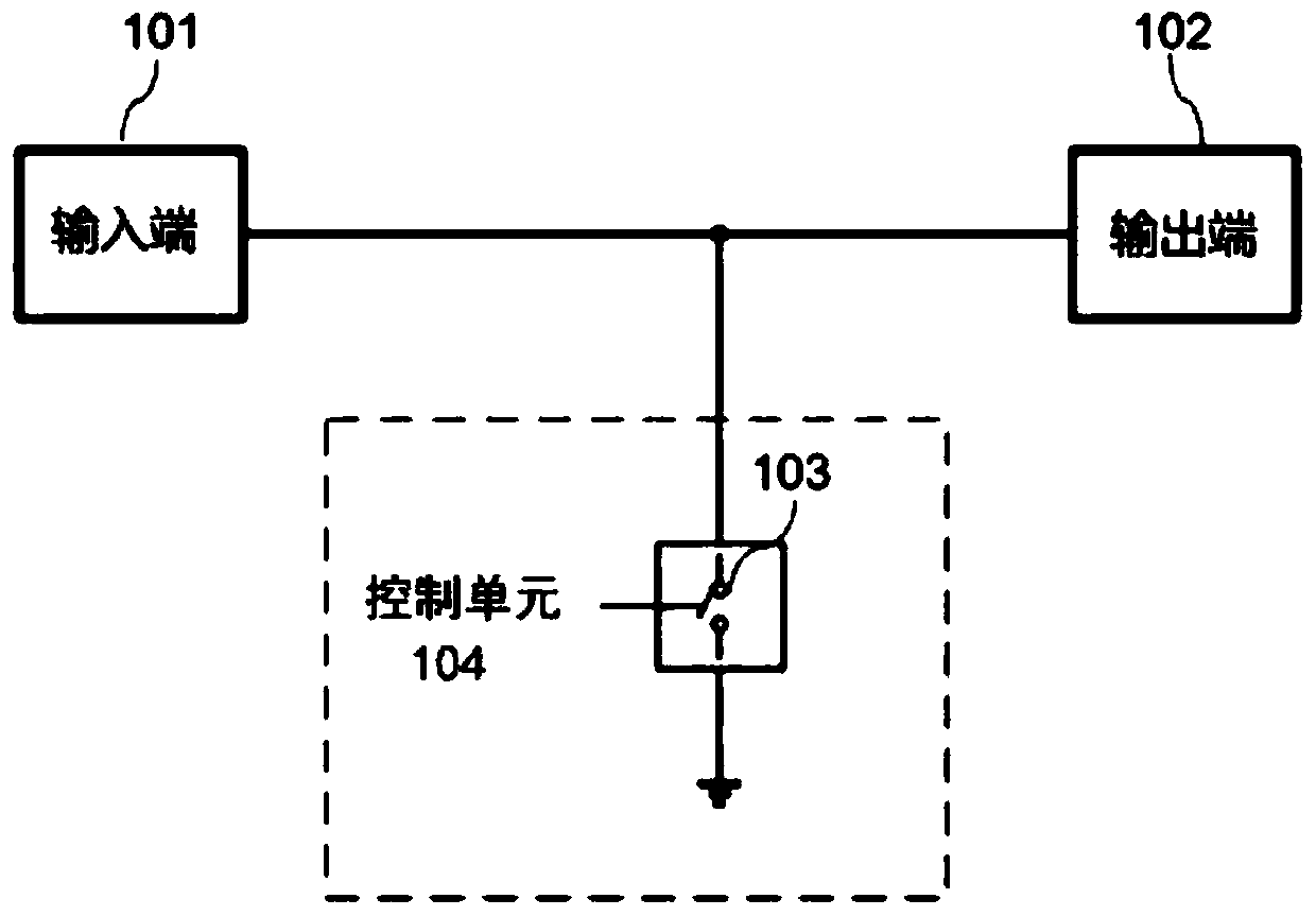
[0047] Embodiment 1 may include a limiter circuit, the circuit includes: a signal input terminal, a signal output terminal, at least one switch tube, and at least one control unit;

[0048] The at least one control unit is used to control the turn-on and turn-off of the at least one switch tube;

[0049] The at least one switch tube is used to weaken the power of the radio frequency signal received by the signal input end and then output it through the signal output end in a conducting state.

Embodiment 2

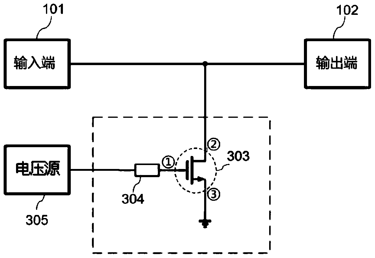
[0050] Embodiment 2 may include the circuit described in Embodiment 1, the limiter circuit further includes at least one resistor corresponding to each of the at least one switch tube, and the first electrode of the switch tube is connected to the corresponding The first end of the resistor, the second end of the resistor is connected to the control unit.

Embodiment 3

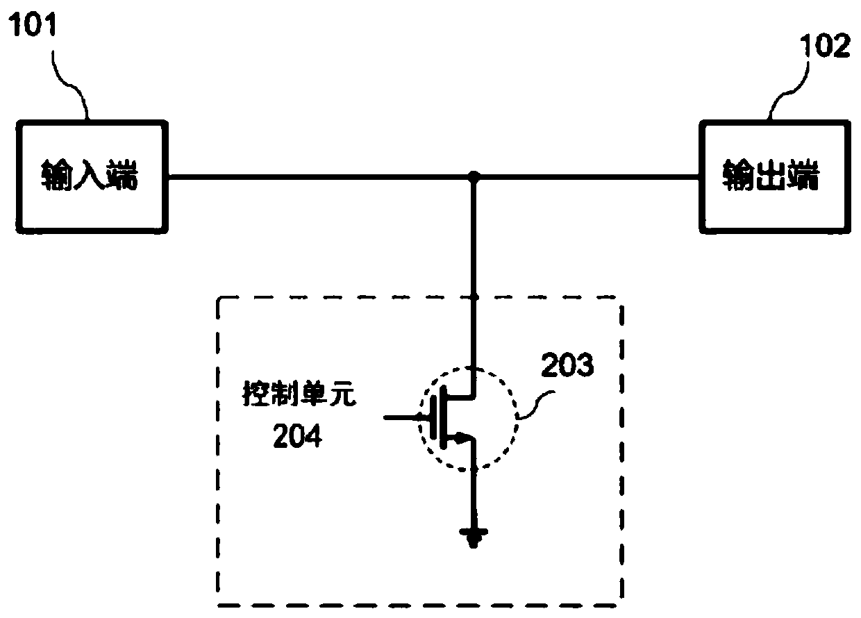
[0051] Embodiment 3 may include the circuit described in Embodiment 1 or 2, the limiter circuit includes a switch tube, wherein the first electrode of the switch tube is connected to the control unit, and the second electrode of the switch tube is connected to The signal input end and the signal output end, and the third electrode of the switch tube are grounded.


PUM


Abstract

The invention discloses an amplitude limiting circuit. The amplitude limiting circuit comprises a signal input end, a signal output end, at least one switching tube and at least one control unit, wherein the at least one control unit is used for controlling connection and disconnection of the at least one switching tube; and the at least one switching tube is used for weakening the power of the radio-frequency signal received by the signal input end in a conduction state and outputting the radio-frequency signal through the signal output end. According to the amplitude limiting circuit disclosed by the invention, the power detector is adopted to control the on and off of the FET, the reduction of the signal power of the signal receiving end is realized, and the switching tubes in the amplitude limiting circuit can be connected in series and in parallel, so that the amplitude limiting circuit can be used for manufacturing small-size amplitude limiting devices.

Description

technical field [0001] The present application relates to radio frequency front-end integrated circuit technology in the field of radio communication and radar technology, and in particular to a limiter circuit. [0002] technical background [0003] In wireless communication, radar, electronic countermeasures and other systems, the transmitter transmits radio signals, and the receiver receives radio signals. Generally speaking, the greater the transmission power of the transmitter, the more beneficial it is for long-distance communication and detection. However, due to the need for high sensitivity, the anti-burnout power that the low-noise receiving circuit at the front end of the receiver can withstand is very small, generally around 10-20dBm . Therefore, there are mainly two situations that will cause damage to the receiver. One situation is that the interference signal with large external power is directly received by the antenna and enters the receiver. If there is no ...

Claims


Application Information

Patent Timeline
Patent Type & Authority Applications(China)
IPC IPC(8): H03K5/08H04B1/16
CPCH03K5/08H04B1/16
Inventor 陆建华柳卫天王曾祺
Owner 上海安其威微电子科技有限公司
Learn More