

Cooking utensil
A technology of cooking utensils and collectors, applied in the field of cooking utensils and cooking utensils that can make low-sugar rice, can solve the problems of high production cost, affecting user experience, complicated structure of separating rice soup, etc., and achieves simple operation, simple structure, and manufacturing cost. low effect
- Summary
- Abstract
- Description
- Claims
- Application Information
AI Technical Summary
Problems solved by technology
Method used
Image

Examples
Embodiment 1
[0037] refer to Figure 1 to Figure 8 , Figure 1 to Figure 8 A first embodiment of the invention is shown.
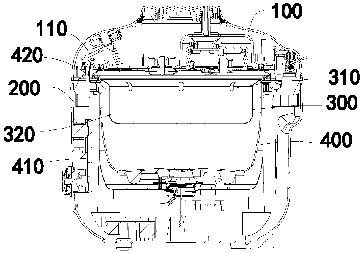
[0038] In this embodiment, the cooking utensil is an electric rice cooker. The electric rice cooker includes a pot body 200 and a pot cover 100. The pot cover 100 and the pot body 200 can be hinged flip buckle or split buckle connection. The pot body 200 includes an outer pot and an inner pot 400 placed in the outer pot. The bottom of the pot body 200 has a heating device, the heating device can be an electromagnetic coil or a heating plate, and the bottom of the pot body 200 is also provided with a bottom temperature measuring part, which is used to detect the temperature of the inner container 400 during cooking.
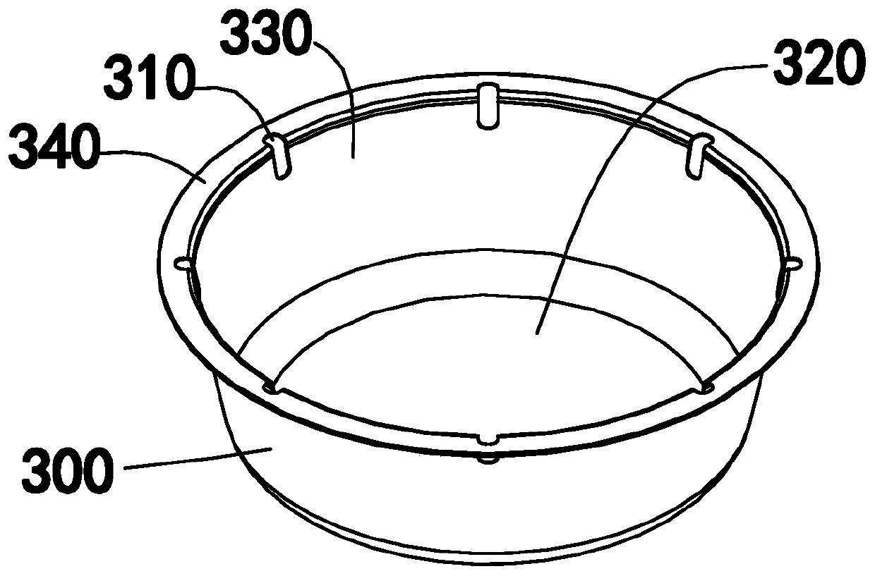
[0039] A rice soup collector 300 is placed on the upper half of the inner container 400, and the rice soup collector 300 has a collection cavity 320, and a rice cooking cavity 410 is formed between the bottom wall of the rice soup collector 300 and the b...
Embodiment 2
[0056] This embodiment is a further improvement of the first embodiment.
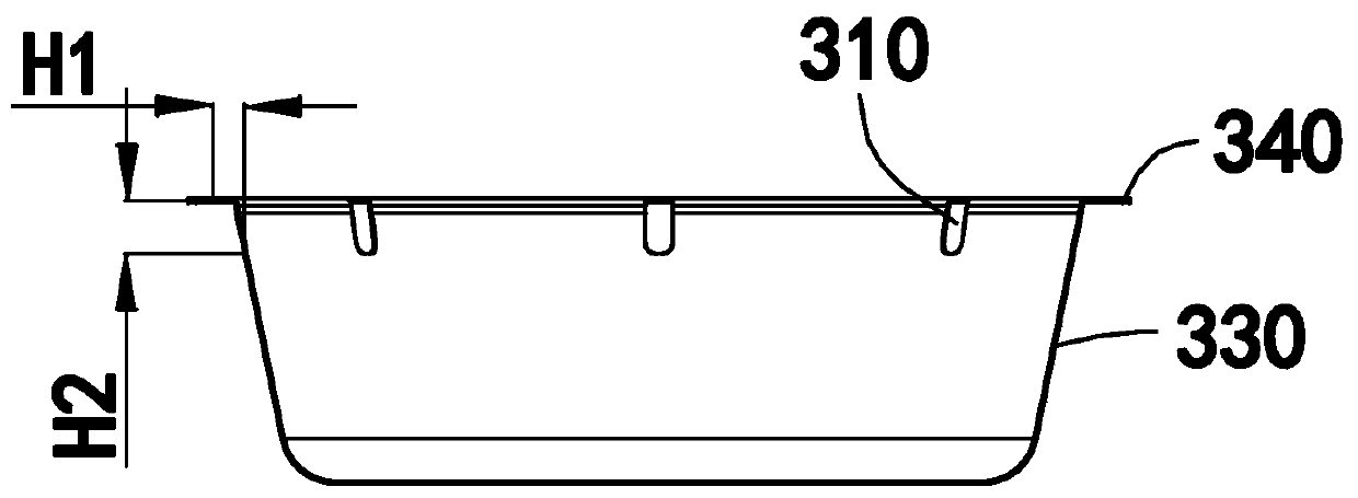
[0057] Reference 9, Figure 9 A second embodiment of the invention is shown. In this embodiment, the width of the rice soup overflow channel 420 between the outer wall 330 of the rice soup collector 300 and the inner wall 330 of the inner tank 400 gradually narrows from bottom to top. When the rice soup is upwelling, the smaller the sectional area of the rice soup overflow channel 420, the greater the pressure of the rice soup upwelling and the faster the speed, the more favorable the rice soup is to enter the collection chamber 320, and the rice soup overflow channel 420 is set as The gradually narrowing structure from bottom to top can make the rice soup have a fast flow velocity and flow pressure when it is close to the through hole 310, so that the rice soup can rush through the through hole 310 and enter the collection chamber 320, improving the effect of rice soup separation.
[0058] Specific...
PUM
 Abstract
Description
Claims
Application Information