Cast steel roller thermal connection device and using method thereof

A cast steel roll and roll technology are applied in the field of cast steel roll heat splicing devices, which can solve the problems of inappropriate roll casting size, low strength of welded joints, insufficient loss size, etc., and achieve the same performance, low cost, and dense finished product structure. Effect

Pending Publication Date: 2019-10-22
成都三强轧辊股份有限公司
View PDF0 Cites 0 Cited by
  • Summary
  • Abstract
  • Description
  • Claims
  • Application Information

AI Technical Summary

Problems solved by technology

However, there are still many rolls whose shape and size are restricted by the casting process, or the size of the loss is not enough during the casting process. For this type of casting, if it cannot be recycled, it will be treated as waste, which consumes a lot of manpower and material resources.
During the use of castings, the size of the roll castings is often inappropriate due to different use requirements. The longer ones can be cut off, and the shorter ones can only be connected with suitable target weldments by welding.
However, the current welding not only has low strength of welded joints and poor tensile properties, but also it is difficult to find suitable weldments for welding

Method used


Image

  • Cast steel roller thermal connection device and using method thereof

Examples


Embodiment 1

[0046] S1. Preheat the rolls to be connected to 280°C and then clean the plane of the rolls to be connected;

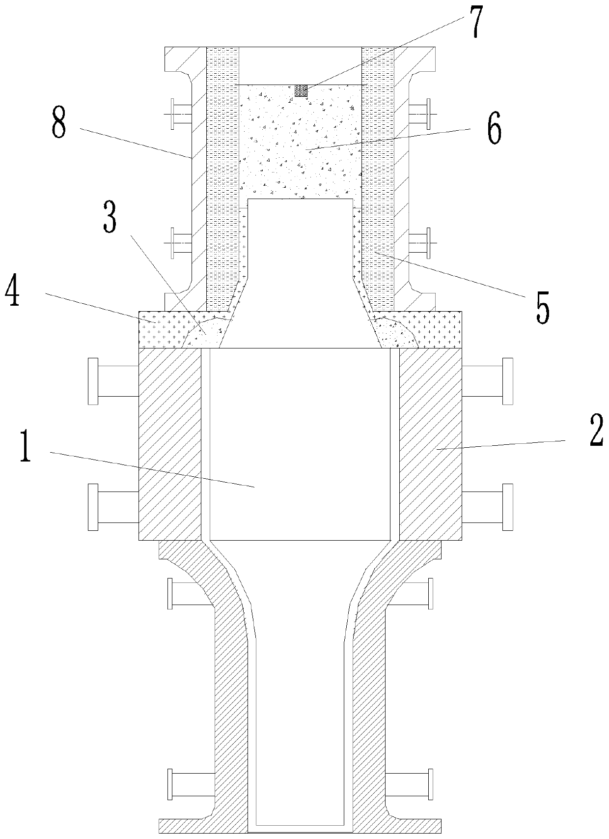
[0047] S2. Clamp and fix the end of the roll to be connected with a fixing piece, then fix the mold at the position to be connected to form a cavity to be connected, fill the cavity to be connected with dry sand, and lay horizontally on the upper layer of the dry sand Water glass 70 sand and blow carbon dioxide to harden;

[0048] S3. Fill the thermal bonding material into the cavity to be connected, and set the ignition material in the thermal bonding material, wherein the component content of the thermal bonding material is: 18 grams of aluminum powder, 60 grams of iron oxide powder, 8 grams of Sodium nitrate, 5 grams of lime, 8 grams of fluorite; the composition content of the ignition material is 3 grams of aluminum powder and 6 grams of sodium nitrate.

[0049] S4. Ignite the ignition material and perform the ignition operation. After the thermal bonding reactio...

Embodiment 2

[0051] Using the same method as in Example 1, the difference is that the preheating temperature of the roll to be joined is 260° C., and the temperature of the molten steel is 1450° C., to obtain a new roll A2 after thermal bonding.

Embodiment 3

[0053] Using the same method as in Example 1, the difference is that the preheating temperature of the rolls to be joined is 300° C., and the temperature of molten steel is 1520° C. to obtain a new roll A3 after thermal bonding.


PUM

PropertyMeasurementUnit
tensile strengthaaaaaaaaaa

Abstract

The invention provides a cast steel roller thermal connection device and a using method thereof. The cast steel roller thermal connection device comprises a to-be-connected roller (1) and a clamping tool (2), wherein the to-be-connected roller is fixedly clamped inside the clamping tool, the clamping tool is clamped below a roller neck of the thermal connection end of the to-be-connected roller, annular dry sand (3) is laid between the to-be-connected roller and the top end surface of the clamping tool, and molding sand (4) is arranged outside the annular dry sand (3); a casting mold (5) is arranged at the upper end of the molding sand (4), and the casting mold (5) is also arranged at the upper end of the to-be-connected roller (1) in a sleeving mode; an auxiliary clamping tool (8) is arranged outside the casting mold (5); and a thermal connection material (6) and an ignition material (7) are arranged above the portion, in the casting mold (5), of the to-be-connected roller (1). By means of the cast steel roller thermal connection device and the using method thereof, the obtained thermally-connected new roller has the advantages that the structure is compact, the performance is thesame as that of a raw material, and a connecting point has higher tensile strength.

Description

technical field [0001] The invention relates to the field of thermal processing and casting, in particular to a cast steel roll thermal bonding device and a method for using the same. Background technique [0002] Cast steel rolls refer to cast steel rolls with a carbon content of 0.4% to 2.1%. According to Chinese classification habits, hypereutectoid cast steel rolls with a carbon content higher than 1.3% are divided into semi-steel rolls and graphite steel rolls according to their structural characteristics; the main carbide in the outer layer of the roll is Cr 7 C 3 It is sometimes called high chromium steel roll. [0003] Static (conventional method) casting cast steel rolls widely use combined vertical casting molds (see the figure below). Metal mold or sand lining (10-30mm) metal mold is used for the roller body. The outer structure of the cast steel roll cast by metal mold is fine and dense. The inner surface of the metal mold is coated with refractory paint, an...

Claims


Application Information

Patent Timeline
Patent Type & Authority Applications(China)
IPC IPC(8): B22D19/04
CPCB22D19/04
Inventor 付家双杨德明李元成
Owner 成都三强轧辊股份有限公司
Why Eureka
Try Eureka