
Self-pressing mechanism based on multi-stage pressure control system of air cylinder

A technology of this pressure mechanism and pressure control, applied in the field of automation, can solve the problems of powerless sensor detection, inconvenient operation, and difficult observation, etc., and achieve the effects of easy production efficiency, good control and adjustment, and high yield rate

Pending Publication Date: 2020-02-28
SHENZHEN XINSANLI AUTOMATION EQUIP
View PDF0 Cites 0 Cited by
  • Summary
  • Abstract
  • Description
  • Claims
  • Application Information

AI Technical Summary

Problems solved by technology

[0002] The structure of the traditional press is complex and inconvenient to operate. The buffer structure of the press is placed in front of the indenter, and it is difficult to observe the binding action of the product when the press head is lowered.
The upper pressure head only uses the cylinder as the movement mechanism, without the detection of the force sensor, the stroke and force control of the upper and lower pressure heads are not accurate, and it is difficult to achieve the accuracy of the product's original pressure

Method used


Image

  • Self-pressing mechanism based on multi-stage pressure control system of air cylinder
  • Self-pressing mechanism based on multi-stage pressure control system of air cylinder
  • Self-pressing mechanism based on multi-stage pressure control system of air cylinder

Examples


Embodiment 1

[0045] Embodiment 1: the concrete structure of the present invention is as follows:

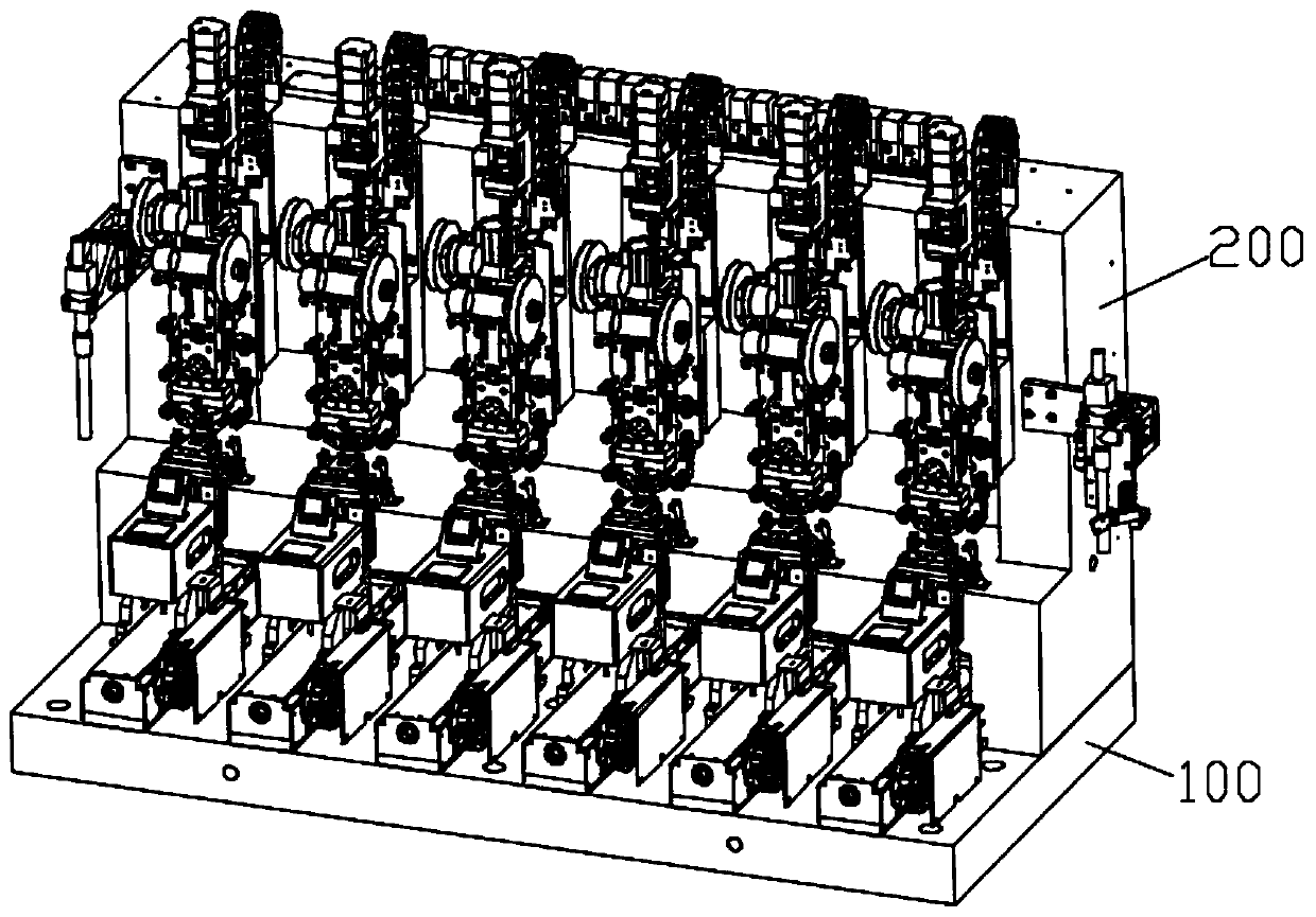
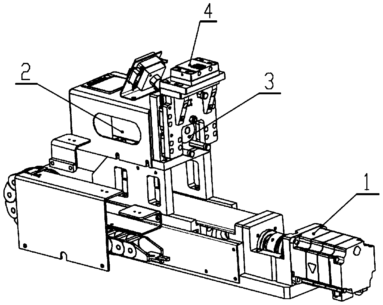
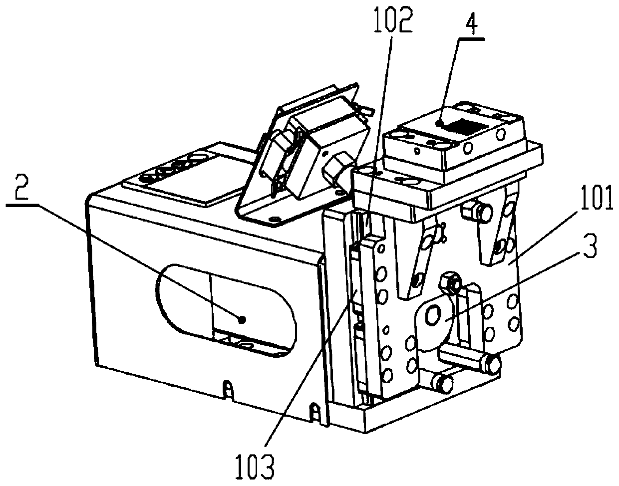
[0046] Please refer to the attached Figure 1-8 , a local pressure mechanism based on a multi-stage pressure control system of a cylinder of the present invention includes an installation assembly and a plurality of groups of local pressure mechanism units installed side by side on the installation assembly, and the installation assembly includes an installation base plate 100 and a The installation vertical plate 200 with a stepped installation position on one side of the upper plate surface of the installation base plate, the installation seat composed of the installation base plate 100 and the installation vertical plate 200 can be installed with at least one local pressure mechanism unit, and the local pressure mechanism unit includes:

[0047]The present pressing platform assembly installed on the mounting base plate 100 includes a platform plate 4 for carrying products, a first Z-axis m...

Embodiment 2

[0075] like Figure 1-8 As shown, the product to be pressed is placed on the platform plate 4, the platform plate 4 opens the vacuum to suck the product, and transports the product to the bottom of the upper indenter through the Y-axis drive mechanism 1, the Y-axis drive mechanism 1 and the first Z The shaft drive mechanism automatically adjusts the position and height of the product.

[0076] Adjust the platform plate 4 to be parallel to the end face of the lower indenter 7. According to the requirements of the temperature and force required by the product, the pulse heating system automatically adjusts the temperature of the upper indenter 18 and the lower indenter 7, and the upper indenter 18 is lowered. The pressure force is constantly detected by the pressure sensor 13, and the pressure sensor 13 constantly feeds back the force situation to the system, and the system automatically adjusts the force of the downward pressure to carry out the original pressure on the product...

Embodiment 3

[0078] The local pressing mechanism based on the cylinder multi-stage pressure control system of the present invention uses the pressure sensor 13 to constantly detect the force exerted on the product when the upper indenter 18 is pressed down, and the stroke control is composed of a servo motor screw and a cylinder, which is convenient for the upper indenter to lower the product. Compression enables stroke and force control. The buffer material feeding structure and buffer material receiving structure are placed above, and the structure is simple. The structure of the guide wheel is used to place the buffer belt above the pressing part of the product. , the upper indenter 18 acts as a buffer for the product when it is pressed down.

[0079] The lower indenter fixing block 6 for installing the lower indenter 7 and the upper indenter fixing block 16 for installing the upper indenter 18 are both made of brass and gold-plated, and the material of the lower indenter 7 and the uppe...


PUM


Abstract

The invention discloses a self-pressing mechanism based on a multi-stage pressure control system of an air cylinder. The self-pressing mechanism comprises a mounting assembly and a plurality of rows of self-pressing mechanism units mounted on the mounting assembly in parallel. The mounting assembly comprises a mounting bottom plate and a mounting vertical plate mounted on one side of an upper panel of the mounting bottom plate. Each self-pressing mechanism unit comprises a self-pressing platform assembly, a lower pressure head assembly and an upper pressure head assembly. The self-pressing platform assembly comprises a platform plate, a first Z-axis mechanism which drives the platform plate to lift to adjust the height and a Y-axis driving mechanism which drives the first Z-axis mechanismto move in a Y-axis direction to adjust the position of the platform plate; the lower pressure head assembly is provided with a lower pressure head to support a product fed by the self-pressing platform; the upper pressure head assembly is provided with a second Z-axis mechanism, a buffer material feeding and receiving structure, a third Z-axis mechanism mounted on a Z-axis moving part of the second Z-axis mechanism and an upper pressure head detachably mounted at the lower end of the third Z-axis mechanism. The self-pressing mechanism can finish a self-pressing action of the product quickly,conveniently, precisely and stably.

Description

technical field [0001] The invention relates to the field of automation technology, in particular to a local pressure mechanism based on a multi-stage pressure control system of a cylinder. Background technique [0002] The traditional pressing structure is complex and the operation is inconvenient. The buffering material structure of the pressing is placed in front of the pressing head, and it is difficult to observe the binding action of the product when the pressing head is lowered. The upper indenter only uses the cylinder as the moving mechanism, and the detection of the sensor is weak, and the control of the stroke and force of the upper and lower indenters is not accurate, so it is difficult to achieve the accuracy of the product's own pressure. SUMMARY OF THE INVENTION [0003] In view of the deficiencies in the prior art, the technical problem to be solved by the present invention is to provide a local pressure mechanism based on a multi-stage pressure control sys...

Claims


Application Information

Patent Timeline
Patent Type & Authority Applications(China)
IPC IPC(8): B30B1/38B30B15/00B30B15/06B30B15/34
CPCB30B1/38B30B15/00B30B15/065B30B15/34
Inventor 李小根师利全胡争光罗东刘强郑明
Owner SHENZHEN XINSANLI AUTOMATION EQUIP
Learn More