
Single-blade hoisting barring gear and method for wind turbine generator system

A wind turbine, single-blade technology, applied in the assembly of wind turbines, wind turbines, control of wind turbines, etc., can solve the problems of limited brake disc width, large motor drive noise and vibration, and increased cost, and meet the requirements of hoisting demand, low vibration and noise, and compact structure

Active Publication Date: 2019-10-22
SHANGHAI ELECTRIC WIND POWER GRP CO LTD
View PDF11 Cites 6 Cited by
  • Summary
  • Abstract
  • Description
  • Claims
  • Application Information

AI Technical Summary

Problems solved by technology

However, this three-blade barring has many disadvantages: first, the brake disc width is limited, and the barring gear is difficult to carry large torque; second, it needs to be equipped with a high-power motor, and the geometric shape and weight of the motor increase geometrically. It is difficult to have enough space in the space; third, the soft start of the motor often needs to be equipped with a frequency converter, resulting in an increase in cost; fourth, the noise and vibration of the motor drive are relatively large
At the same time, in the existing technology, it is impossible to automatically judge whether the hub mouth has reached the designated position, especially when installing the first blade, it is necessary to manually judge whether the position of the hub mouth is horizontal
[0005] There is no single-blade hoisting bar car in China to meet the market demand, and the imported products have complex structures, high costs, and difficult maintenance

Method used


Image

  • Single-blade hoisting barring gear and method for wind turbine generator system
  • Single-blade hoisting barring gear and method for wind turbine generator system
  • Single-blade hoisting barring gear and method for wind turbine generator system

Examples


Embodiment Construction

[0041] The following will clearly and completely describe the technical solutions in the embodiments of the present invention with reference to the accompanying drawings in the embodiments of the present invention. Obviously, the described embodiments are only some, not all, embodiments of the present invention. Based on the embodiments of the present invention, all other embodiments obtained by persons of ordinary skill in the art without making creative efforts belong to the protection scope of the present invention.

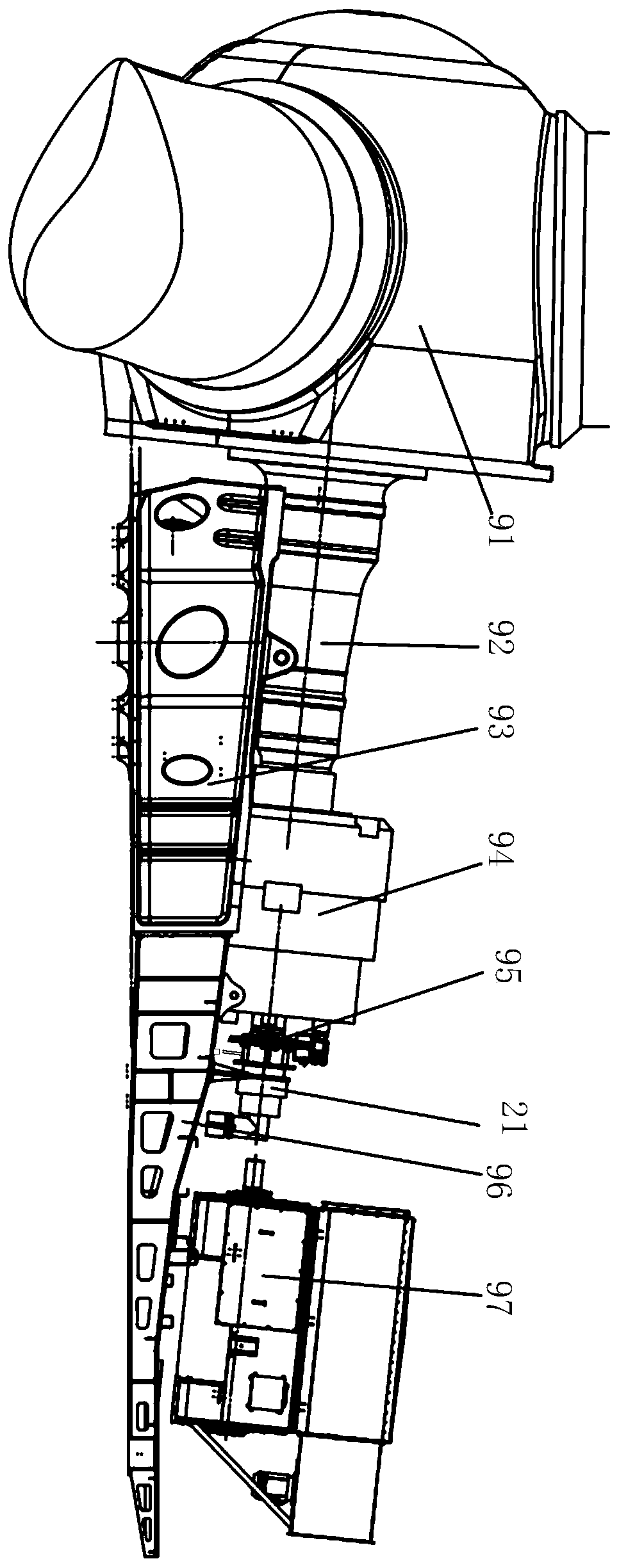
[0042]In the wind power generating set in the prior art, the blades and the hub are assembled together to form the impeller 91, the impeller 91, the main shaft 92, the gear box 94, and the generator 97 form the transmission chain of the wind power generating set, the impeller 91 rotates to drive the main shaft 92, and the main shaft 92 The output shaft of the gear box 94 is driven to rotate, and the rotor of the generator is driven to rotate through the output ...


PUM


Abstract

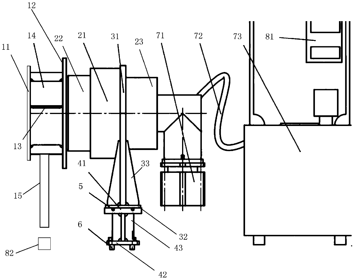
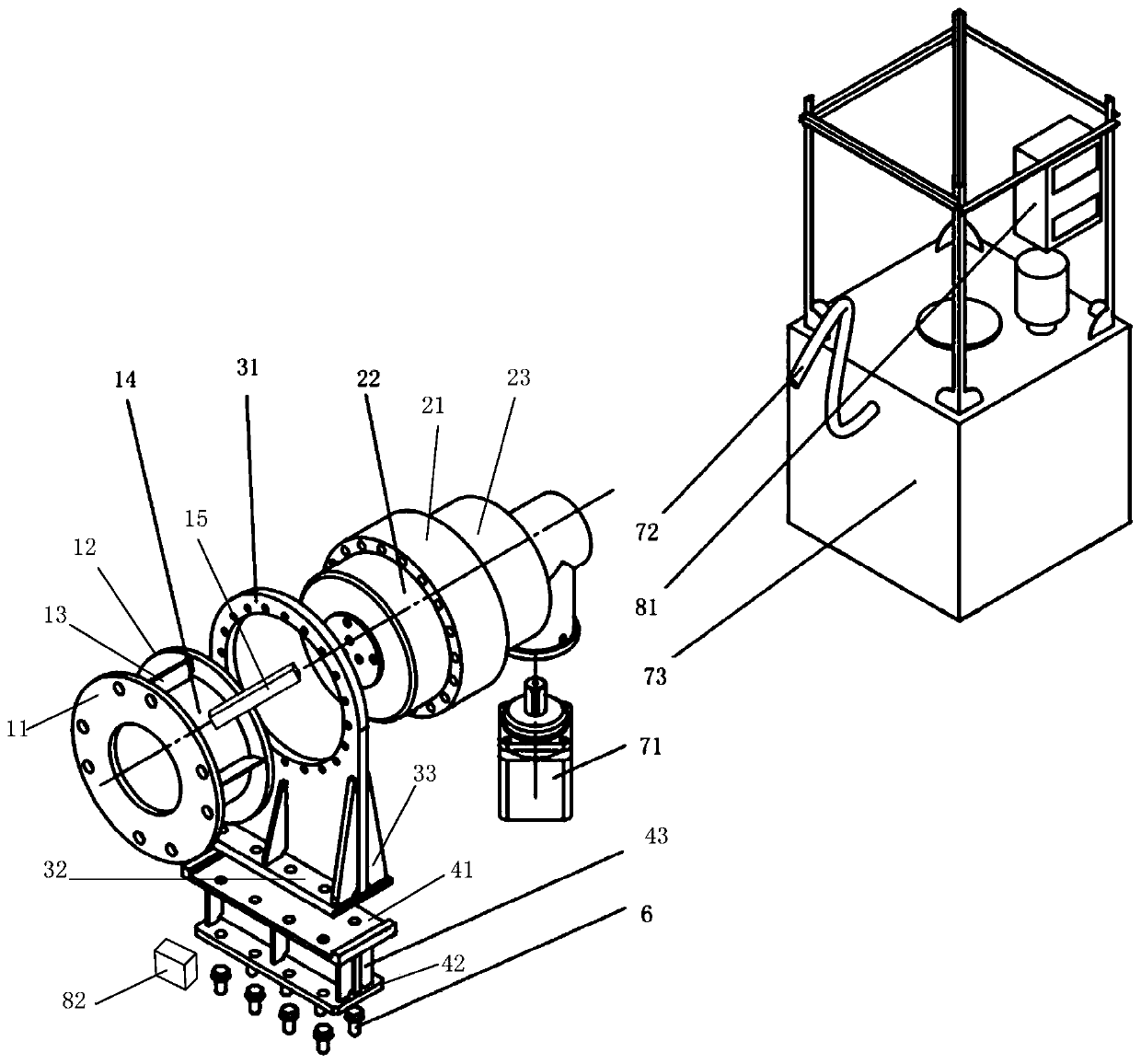
The invention provides a single-blade hoisting barring gear for a wind turbine generator system. The single-blade hoisting barring gear comprises a barring unit, a power system and a control system, the barring unit comprises a decelerator and a conversion flange, the decelerator is connected with a brake disc on an output shaft of a gearbox through the conversion flange, the power system is connected with an input shaft of the decelerator, and by driving the input shaft of the decelerator to rotate radially, an output shaft of the decelerator drives the output shaft of the gearbox to rotate radially; and the control system is connected with the power system, and the power system is controlled to start or stop working according to obtained position information of a hub opening. The position information of the hub opening can be automatically obtained, the rotating amplitude of an impeller is automatically controlled, during single-blade hoisting of the wind turbine generator system, the hub opening is kept at the horizontal position, and the single-blade hoisting demands of the wind turbine generator system are met. The single-blade hoisting barring gear is small in size and compact in structure, large moment of force can be stably output through a hydraulic motor to drive the impeller to rotate, vibration noise is small, and the safety of hydraulic pressure-maintaining brakingis higher.

Description

technical field [0001] The invention relates to the field of wind power generating equipment, in particular to a single-blade hoisting and barring device for a wind power generating set. Background technique [0002] The existing wind turbine blade assembly technology is to assemble the three blades and the hub to form an integral part on the ground or sea level platform of the wind field, and then use one or more cranes to coordinate and hoist the part to the nacelle at an altitude of about 100 meters The front end finally completes the assembly of the entire fan. The disadvantage of the prior art is that a sufficiently large platform or open space is required at the attachment of the stand tower. With the increase of the blades, the requirements for the platform and open space become larger and larger. [0003] As the excellent wind resource market has been gradually developed in the early stage, more and more sub-excellent wind resources in mountains and hills have gradu...

Claims


Application Information

Patent Timeline
IPC IPC(8): F03D13/10F03D7/04
CPCF03D7/0248F03D7/04F03D13/10Y02E10/72
Inventor 马金国马文勇王立恒
Owner SHANGHAI ELECTRIC WIND POWER GRP CO LTD
Learn More