Device with clamping mechanism and for finish machining of steel plate

A clamping mechanism and steel plate technology, which is applied to metal processing machinery parts, positioning devices, manufacturing tools, etc., can solve the problems of falling, weak steel plate clamping, steel plate deviation, etc., and achieve the effect of improving stability

Inactive Publication Date: 2019-10-25
DONGGUAN KAILEDI NUMERICAL CONTROL SCI & TECH CO LTD
View PDF1 Cites 5 Cited by
  • Summary
  • Abstract
  • Description
  • Claims
  • Application Information

AI Technical Summary

Problems solved by technology

[0005] Aiming at the deficiencies of the prior art, the present invention provides a device with a clamping mechanism for steel plate finishing, which solves the problem that the currently used steel plate clamping device proposed in the above background technology does not clamp the steel plate firmly, so that in the During the clamping process, the steel plate is prone to deviation or drop

Method used


Image

  • Device with clamping mechanism and for finish machining of steel plate
  • Device with clamping mechanism and for finish machining of steel plate
  • Device with clamping mechanism and for finish machining of steel plate

Examples


Embodiment Construction

[0028] The following will clearly and completely describe the technical solutions in the embodiments of the present invention with reference to the accompanying drawings in the embodiments of the present invention. Obviously, the described embodiments are only some, not all, embodiments of the present invention.

[0029] In the description of the present invention, unless otherwise stated, the meaning of "plurality" is two or more; the terms "upper", "lower", "left", "right", "inner", "outer" , "front end", "rear end", "head", "tail", etc. indicate the orientation or positional relationship based on the orientation or positional relationship shown in the drawings, and are only for the convenience of describing the present invention and simplifying the description, rather than Indicates or implies that the device or element referred to must have a particular orientation, be constructed and operate in a particular orientation, and therefore should not be construed as limiting the...


PUM

PropertyMeasurementUnit
widthaaaaaaaaaa
widthaaaaaaaaaa

Abstract

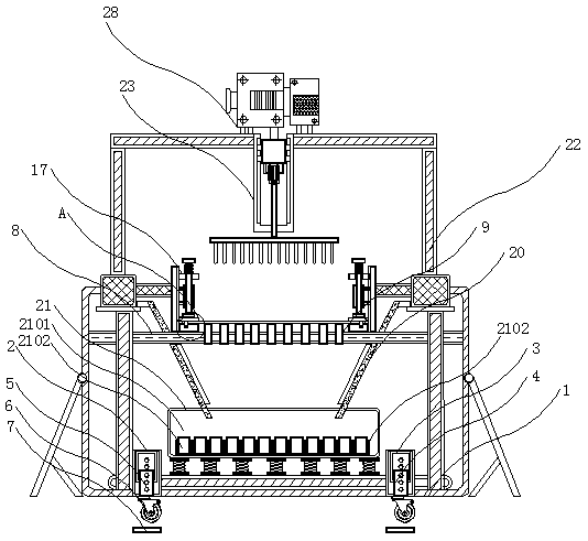
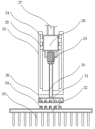
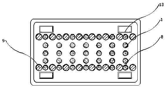
The invention discloses a device with a clamping mechanism and for finish machining of a steel plate, and relates to the steel plate processing technology field. The device with the clamping mechanismand for the finish machining of the steel plate specifically comprises a work base frame, a workbench and a connection frame, wherein an embedded frame is connected with the inner wall of the work base frame in a penetration mode, a limiting strip is fixedly welded above the workbench, a compression mechanism is installed in a limiting groove, a drainage plate is connected with the inner wall ofthe workbench in a penetration mode, the connection frame is connected with the upper end of the work base frame through a screw, a work plate is fixedly welded on the inner wall of the middle of theconnection frame, a slide groove is formed in the edge of the inner wall of the work plate, a slide block is installed in the slide groove, and a moving block is fixedly bonded in the slide block. Thedevice with the clamping mechanism and for the finish machining of the steel plate can freely stretch a telescopic rod to a proper position so as to facilitate distance regulation between a telescopic sleeve and the telescopic rod, and therefore the device with the clamping mechanism and for the finish machining of the steel plate can be integrally moved and transported, and during the contracting process of a trundle, stable performance in overall work of the device with the clamping mechanism and for the finish machining of the steel plate can be improved.

Description

technical field [0001] The invention relates to the related technical field of steel plate processing, in particular to a device with a clamping mechanism for finishing steel plate. Background technique [0002] The width of the thin plate is 500-1500 mm, and the width of the thick plate is 600-3000 mm. The thin plate is divided into steel types, including ordinary steel, high-quality steel, alloy steel, spring steel, stainless steel, tool steel, heat-resistant steel, bearing steel, and silicon steel. And industrial pure iron sheets, etc., according to professional purposes, there are oil drum plates, enamel plates, bulletproof plates, etc. , because the steel plate is made of mixed raw materials, the steel plate needs to be processed in the process of production and processing, so as to facilitate the subsequent operation and sales of the steel plate by the user, so the steel plate needs to be clamped in the production process, Subsequent processing can be carried out on t...

Claims


Application Information

Patent Timeline
Patent Type & Authority Applications(China)
IPC IPC(8): B23B39/16B23Q3/06B23Q11/00
CPCB23B39/161B23Q3/06B23Q11/0064B23Q11/0067
Inventor 邓玲凤丘强邱广文陈马鑫
Owner DONGGUAN KAILEDI NUMERICAL CONTROL SCI & TECH CO LTD
Why Eureka
Try Eureka